
Method for detecting luminous intensity and uniformity based on CCD perception

A detection method and luminous intensity technology, applied in 3D image processing, 3D modeling, image enhancement, etc., can solve problems such as fitting, not being able to adapt well to different display devices, and unable to achieve accurate detection of specific products.

Pending Publication Date: 2021-05-07
WUHAN HAIWEI TECH CO LTD
View PDF0 Cites 0 Cited by
  • Summary
  • Abstract
  • Description
  • Claims
  • Application Information

AI Technical Summary

Problems solved by technology

[0002] With the acceleration of the upgrading of flat-panel displays, users have higher and higher requirements for the display effect of display devices, and the high requirements for production efficiency in the mass production process make the traditional point-type luminance meter unable to meet the test requirements.
The traditional brightness and uniformity detection methods are mainly 5-point and 9-point methods, etc., which leads to extremely low efficiency when full-screen detection is required. Whether it is an automatic or semi-automatic production line, it takes a long time and cannot meet the requirements. Production line needs
[0003] In addition, traditional methods are not good for small-scale luminance detection, and some methods have complicated calibration processes. For different products, the calibration method is single and cannot be well adapted to different display devices.
Some equipment cannot realize the measurement of luminance at any point
In the automatic detection of display devices, the brightness of display devices shows a certain trend. Traditional algorithms cannot fit this trend well for specific products, and cannot achieve accurate detection of specific products.
Some detection equipment is susceptible to noise interference

Method used


Image

  • Method for detecting luminous intensity and uniformity based on CCD perception
  • Method for detecting luminous intensity and uniformity based on CCD perception
  • Method for detecting luminous intensity and uniformity based on CCD perception

Examples


Embodiment Construction

[0048] The principles and features of the present invention will be described below with reference to the accompanying drawings. The examples are only used to explain the present invention, but not to limit the scope of the present invention.

[0049] A detection method of luminous intensity and uniformity based on CCD perception, comprising the following steps:

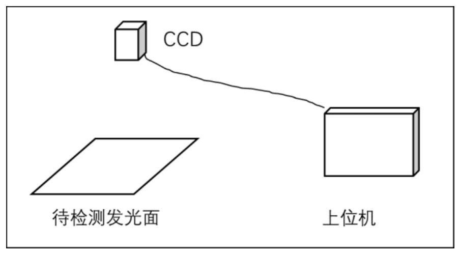
[0050] Step a1, take the light-emitting surface to be measured, and set the parameters of the CCD, including parameters such as focal length f, aperture F, gain GA, white balance parameter BA, exposure time T and working distance L, so that they are the same as the GCD parameters in the calibration step;

[0051] Step a2, in a dark room environment, imaging the luminous surface to be measured to obtain an imaging image I;

[0052] Step a3, extract the brightness feature matrix M and the uniformity feature U of the imaging image I, and the extraction process specifically includes the following steps:

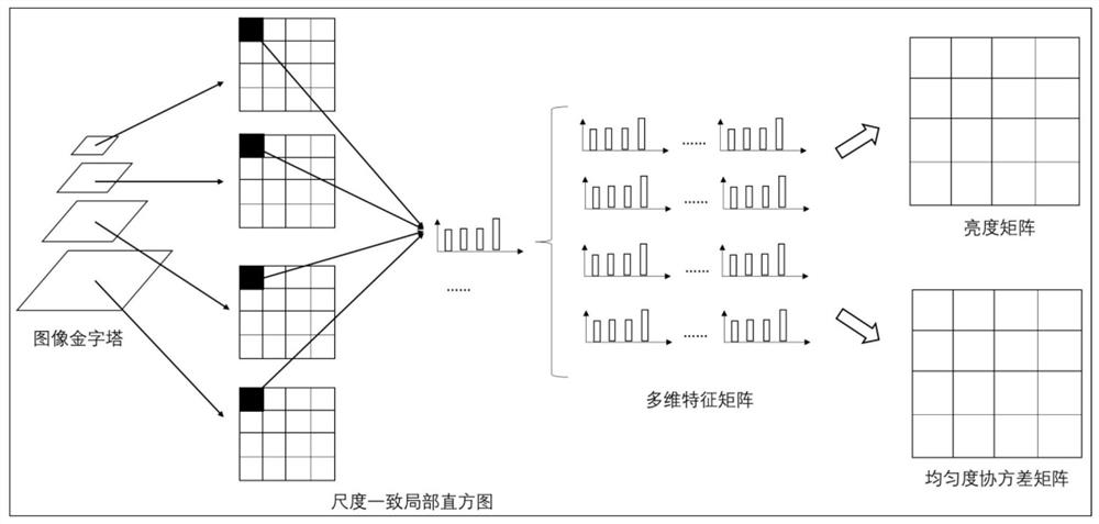
[0053] Step a3...


PUM


Abstract

The invention relates to a method for detecting luminous intensity and uniformity based on CCD perception, and the method comprises a calibration step and a detection step, and the detection step comprises the following steps: a1, taking a luminous surface to be detected, and setting parameters of a CCD to be the same as the parameters of the CCD in the calibration step; a2, in a darkroom environment, imaging a light-emitting surface to be measured to obtain an imaging image I; a3, extracting a brightness characteristic matrix M and a uniformity characteristic U of the imaging image I; a4, establishing and learning a brightness model according to the calibration step to obtain a learned brightness model; a5, calculating the brightness A of the light-emitting surface to be measured according to the learned brightness model and the brightness characteristic matrix; and calculating the uniformity u of the light-emitting surface to be measured according to the uniformity characteristic matrix U. According to the invention, brightness and uniformity detection of different light-emitting materials can be realized, detection of different light-emitting positions and different light-emitting sizes can be realized, noise interference can be resisted, and the method is simple and easy to implement.

Description

technical field [0001] The invention relates to the technical field of luminous surface detection, in particular to a detection method of luminous intensity and uniformity based on CCD perception. Background technique [0002] With the acceleration of the upgrading of flat panel displays, users have higher and higher requirements for the display effect of display devices, as well as high requirements for production efficiency in the process of mass production, making the traditional point luminance meter unable to meet the test requirements. The traditional brightness and uniformity detection methods are mainly 5-point and 9-point methods, etc., which leads to low efficiency when full-screen detection is required. Whether it is an automatic or semi-automatic production line, it takes a long time and cannot be satisfied. production line needs. [0003] In addition, the traditional method is not good for the detection of luminous brightness in a small range, and the calibrati...

Claims


Application Information

Patent Timeline
IPC IPC(8): G06T15/50G06T17/00G06T7/80G06K9/62
CPCG06T15/506G06T17/00G06T7/80G06T2207/20081G06T2207/30244G06F18/214
Inventor 胡伦庭林碧云
Owner WUHAN HAIWEI TECH CO LTD
Learn More