Counter electromotive force detection device of motor and motor

A technology of back electromotive force and detection device, used in electronic commutation motor control, single motor speed/torque control, electrical components, etc., can solve the problem of difficult positioning of brushless DC motors, and achieve the effect of reducing the difficulty of rotor positioning

Pending Publication Date: 2021-05-07
GREE ELECTRIC APPLIANCES INC OF ZHUHAI +1
View PDF4 Cites 0 Cited by
  • Summary
  • Abstract
  • Description
  • Claims
  • Application Information

AI Technical Summary

Problems solved by technology

[0006] The object of the present invention is to provide a back electromotive force detection device and a motor to solve the problem that the rotor positioning of the brushless DC motor is relatively difficult, and to achieve the purpose of detecting the back electromotive force of the motor by setting a back electromotive force detection circuit. Electromotive force, the rotor positioning of the motor is realized according to the counter electromotive force, and the effect of reducing the difficulty of rotor positioning of the brushless DC motor

Method used


Image

  • Counter electromotive force detection device of motor and motor
  • Counter electromotive force detection device of motor and motor

Examples


Embodiment Construction

[0022] In order to make the purpose, technical solution and advantages of the present invention clearer, the technical solution of the present invention will be clearly and completely described below in conjunction with specific embodiments of the present invention and corresponding drawings. Apparently, the described embodiments are only some of the embodiments of the present invention, but not all of them. Based on the embodiments of the present invention, all other embodiments obtained by persons of ordinary skill in the art without making creative efforts belong to the protection scope of the present invention.

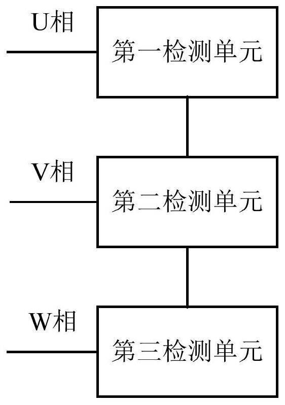
[0023] According to an embodiment of the present invention, a device for detecting back electromotive force of a motor is provided. see figure 1 A schematic structural view of an embodiment of the device of the present invention is shown. The back electromotive force detection device of the motor may include: a first detection unit (such as a U opposite electrom...


PUM


Abstract

The invention discloses a counter electromotive force detection device of a motor and the motor. The device comprises a first detection unit which is configured to detect the U-phase counter electromotive force of the motor as a U-phase detection potential, a second detection unit configured to detect a back electromotive force of a V-phase of the motor as a V-phase detection potential, and a third detection unit configured to detect a back electromotive force of a W-phase of the motor as a W-phase detection potential; the first detection unit can be coupled with the second detection unit and the third detection unit to generate a neutral point potential of the motor as a reference potential so as to determine a commutation moment of the motor based on the reference potential according to the U-phase detection potential, the V-phase detection potential and the W-phase detection potential. According to the scheme, the counter electromotive force detection circuit is arranged, the counter electromotive force of the motor is detected through the counter electromotive force detection circuit, rotor positioning of the motor is achieved according to the counter electromotive force, and the rotor positioning difficulty of the brushless direct current motor is reduced.

Description

technical field [0001] The invention belongs to the technical field of motors, in particular to a back electromotive force detection device and a motor, in particular to a back electromotive force detection circuit and a motor (such as a permanent magnet brushless DC motor). Background technique [0002] The working principle of the brushless DC motor must have information related to the position of the rotor magnetic field to control the switching on or off of the power device in the inverter to realize the commutation of the stator winding. When the brushless DC motor commutates, it is necessary to detect the rotor position information, but the detection of the rotor position information is relatively difficult. [0003] In related solutions, the rotor position information of the brushless DC motor is directly detected by electromechanical or electronic sensors, such as Hall sensors and photoelectric sensors. The structure and control circuit of the square wave brushless...

Claims


Application Information

Patent Timeline
IPC IPC(8): H02P6/182H02P6/08
CPCH02P6/182H02P6/08
Inventor 张敏郭春林刘丽刚王科林锰津王城
Owner GREE ELECTRIC APPLIANCES INC OF ZHUHAI
Why Eureka
Try Eureka