Noise suppression high-voltage level shift circuit based on delay self-locking

A level shifting circuit and noise suppression technology, which is applied in the direction of logic circuit coupling device, logic circuit connection/interface arrangement, reliability improvement and modification, etc., can solve problems such as occupying a large layout area, high technical threshold, and increasing product cost. , to achieve high reliability and application value, suppress the transmission path, and occupy a small area

Pending Publication Date: 2021-05-07
NAT SUPERCOMPUTING WUXI CENT
View PDF0 Cites 0 Cited by
  • Summary
  • Abstract
  • Description
  • Claims
  • Application Information

AI Technical Summary

Problems solved by technology

For bypass capacitor common-mode noise suppression circuits, high-voltage capacitor technology is generally required, which has a high technical threshold and is difficult to implement
For the noise interlock circuit composed of gate-source short-connected LDMOS power transistor and PMOS, the redundant LDMOS transistor will occupy a large layout area, which greatly increases the product cost
In addition, the noise suppression circuit using multiple differential amplifiers also faces the problems of circuit matching and high-voltage stability, and there are certain risks in specific applications.

Method used


Image

  • Noise suppression high-voltage level shift circuit based on delay self-locking
  • Noise suppression high-voltage level shift circuit based on delay self-locking
  • Noise suppression high-voltage level shift circuit based on delay self-locking

Examples


Embodiment 1

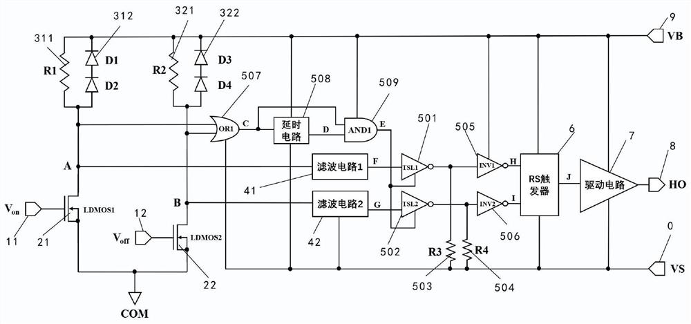
[0022] Such as image 3As shown, a noise suppression high-voltage level shift circuit based on delay self-locking is characterized in that it includes an input port 1, a level shift circuit 2, a voltage clamp circuit 3, a filter circuit 4, and a delay self-locking circuit 5. RS flip-flop 6, drive circuit 7, output port 8, high voltage bias port 9 and high voltage floating ground port 0; input port 1 includes first input port 11 and second input port 12; level shift circuit 2 includes the first An LDMOS transistor 21, a second LDMOS transistor 22; the voltage clamp circuit 3 includes a first clamp circuit 31 and a second clamp circuit 32; the first input port 11 is connected to the gate of the first LDMOS transistor 21; the first LDMOS transistor The source of 21 is grounded, and the drain of the first LDMOS transistor 21 is connected to the high voltage bias port 9 through the first clamp circuit 31; the second input port 12 is connected to the gate of the second LDMOS transis...


PUM


Abstract

The invention provides a self-locking noise suppression circuit based on noise signal delay superposition, by reasonably setting the locking pulse width of the noise signal, the propagation path of the noise signal can be effectively suppressed, and meanwhile, the propagation of a normal working signal is not influenced; and the circuit structure and the used modules are simple, the occupied area is small, and the reliability and the application value are relatively high.

Description

technical field [0001] The invention relates to a noise-suppressing high-voltage level shift circuit, in particular to a noise-suppressing high-voltage level shift circuit based on time-delay self-locking. Background technique [0002] The high-voltage level shift circuit is mainly used to turn on the high-side MOSFET or IGBT power transistor, and is a key circuit for converting low-voltage logic signals to high-voltage signals. In order to realize the correct turn-on and turn-off of the high-side power transistor, its gate voltage V gs The level range is changed between the high-voltage power supply VB and the floating ground VS to ensure that the gate-source voltage difference is greater than the turn-on threshold voltage of the power transistor. For traditional narrow pulse trigger level shift circuits (such as figure 1 ), the floating ground VS will float between 0V and high voltage, and then generate dV / dt noise in the circuit. The large dV / dt noise can generate disp...

Claims


Application Information

Patent Timeline
Patent Type & Authority Applications(China)
IPC IPC(8): H03K19/003H03K19/0175
CPCH03K19/003H03K19/017545
Inventor 刘天奇杨广文蔡畅陈更生甘霖
Owner NAT SUPERCOMPUTING WUXI CENT
Why Eureka
Try Eureka