Agricultural drip irrigation device

An agricultural and water tank technology, applied in agriculture, watering devices, climate change adaptation, etc., can solve problems such as unfavorable energy saving and environmental protection production requirements, water waste, and difficulty in controlling water supply.

Inactive Publication Date: 2021-05-11
赵辛迪
View PDF8 Cites 0 Cited by
  • Summary
  • Abstract
  • Description
  • Claims
  • Application Information

AI Technical Summary

Problems solved by technology

[0003] The existing drip irrigation device sends water through the pipeline, and then drops the water on the crops through a small pipe head. The frequency of water supply can be realized by controlling the water flow pressure. There is still a lot of water, resulting in a waste o

Method used


Image

  • Agricultural drip irrigation device
  • Agricultural drip irrigation device
  • Agricultural drip irrigation device

Examples


Embodiment 1

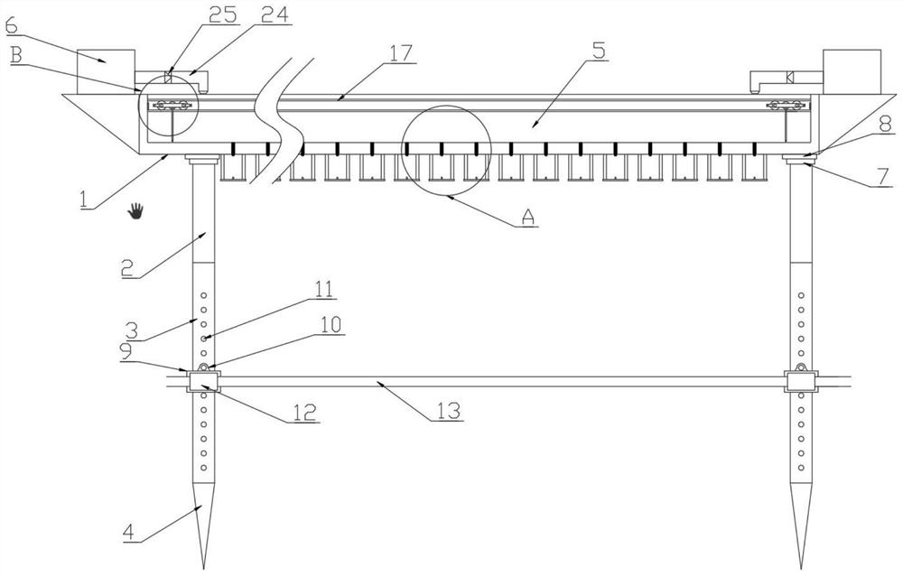
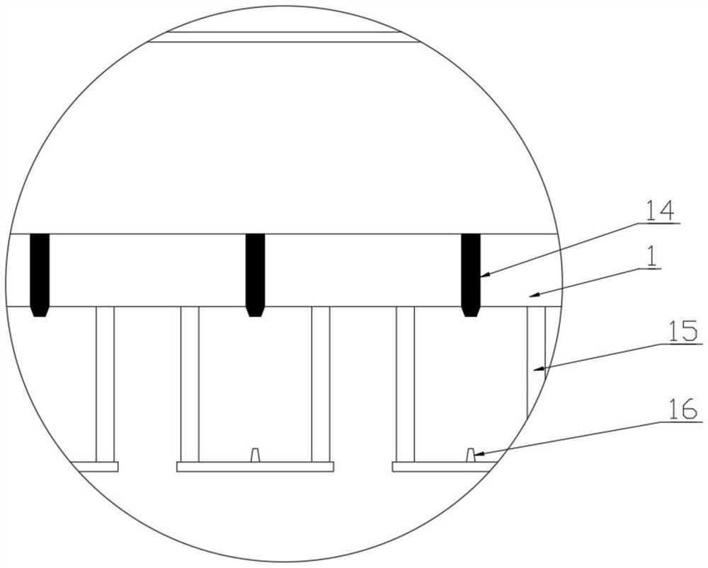
[0022] Please refer to the figure, in the embodiment of the present invention, an agricultural drip irrigation device includes a water tank 1, a sliding sleeve 2, a telescopic rod 3, a spike part 4, a wiper chamber 5 and a water tank 6; Both ends of 1 are provided with a vertical sliding sleeve 2, and the lower end of the sliding sleeve 2 slides through a vertical telescopic rod 3, and the telescopic rod 3 and the water tank 1 are fixed by fastening bolts, which is convenient for adjusting the sliding Cover 2, the length of the telescopic rod 3, thereby adjusting the height of the water tank 1; the lower end of the telescopic rod 3 is fixed with a vertically downward spiked part 4, through which the spiked part 4 can be inserted into the soil, and the drip irrigation device is fixed Above the crops; both ends of the water tank 1 are fixed with a water tank 6, which is connected by a pipeline water supply device to supply water to the water tank 6, and the bottom of the water ta...

Embodiment 2

[0027]On the basis of Embodiment 1, the outer sliding sleeve of the telescopic rod 3 is provided with a lifting seat 9, and the lifting seat 9 moves up and down on the outside of the telescopic rod 3, and the lifting seat 9 is fixedly provided with a positioning seat 10, and a Pin holes, insert positioning pins in the pin holes, several adjustment holes 11 are provided on the telescopic rod 3 corresponding to the pin holes on the positioning seat 10, and the adjustment holes 11 are arranged at equal intervals in the vertical direction, inserted into the In the adjustment holes 11 of different heights, the height of the lifting seat 9 is adjusted; the connecting seat 12 is connected with a universal joint on the lifting seat 9, and the connecting seat 12 is a hollow tube structure, and the connecting seat 12 can be adjusted to different directions. There is a hanging bar 13 passing through the connecting seat 12, and the hanging bar 13 is supported by the connecting seat 12. Adj...


PUM


Abstract

The invention relates to the field of agricultural planting, and particularly discloses an agricultural drip irrigation device. The agricultural drip irrigation device comprises a water tank, sliding sleeves, telescopic rods, spine parts, a water scraping cavity and water tanks, wherein a plurality of holes are formed in the bottom of the water scraping cavity, a water dripping sponge head extending downwards to the position below the water tanks is fixedly installed in each hole, when water exists above the water scraping cavity, the water makes contact with the water dripping sponge heads and slowly flows downwards along the water dripping sponge heads, a rotating shaft perpendicular to guide rails is arranged in a vehicle frame in a penetrating mode, the two ends of the rotating shaft are rotationally connected with rolling wheels located in the guide rails through bearings, a motor is installed on the vehicle frame, and a water scraping plate vertically extending downwards to the bottom of the water scraping cavity is fixedly installed on the vehicle frame. By means of the water scraping plate capable of moving in the water scraping cavity, a small amount of water entering the water scraping cavity is pushed in the water scraping cavity, makes contact with the water dripping sponge in the pushing process, flows downwards on the water dripping sponge, is accumulated at the bottom of the water scraping cavity and is slowly gathered into water drops to fall down.

Description

technical field [0001] The invention relates to the field of agricultural planting, in particular to an agricultural drip irrigation device. Background technique [0002] Drip irrigation equipment is a combination of irrigation tools used in drip irrigation technology, collectively referred to as drip irrigation equipment. Drip irrigation equipment includes: drippers on pipes, drip irrigation belts, drip irrigation pipes, drip irrigation with continuous patch type, side seam type, double wall type, and inlaid Chip type, drip irrigation pipes are divided into inner panel type and inner column type, drip irrigation emitters are also divided into non-pressure compensation and pressure compensation type, drip irrigation equipment is mainly used in wide rows, high economic value crops such as trees, cotton, potatoes, vegetables In the irrigation of crops, nurseries, greenhouses, etc., during the drip irrigation process, fertilizers can be mixed into the water to provide nutrients...

Claims


Application Information

Patent Timeline
IPC IPC(8): A01G25/02A01G25/16
CPCA01G25/02A01G25/16Y02A40/22
Inventor 赵辛迪
Owner 赵辛迪
Why Eureka
Try Eureka