Sewage tank structure for cleaning equipment and cleaning equipment

A technology for cleaning equipment and waste water tanks, applied in cleaning equipment, cleaning machinery, applications, etc., to improve space utilization, avoid damage to suction generating devices, and reduce the probability of damage

Pending Publication Date: 2021-05-11
KEEWOO ROBOTICS TECH CO LTD
View PDF0 Cites 7 Cited by
  • Summary
  • Abstract
  • Description
  • Claims
  • Application Information

AI Technical Summary

Problems solved by technology

[0003] Based on this, it is necessary to provide a sewage tank structure and cleaning equipment for cleaning equipment in view of the problem that the sewage garbage in the sewage tank of the existing wet vacuum cleaner is sucked into the motor

Method used


Image

  • Sewage tank structure for cleaning equipment and cleaning equipment
  • Sewage tank structure for cleaning equipment and cleaning equipment
  • Sewage tank structure for cleaning equipment and cleaning equipment

Examples


Embodiment Construction

[0046] In order to make the above objects, features and advantages of the present invention more comprehensible, specific implementations of the present invention will be described in detail below in conjunction with the accompanying drawings. In the following description, numerous specific details are set forth in order to provide a thorough understanding of the present invention. However, the present invention can be implemented in many other ways different from those described here, and those skilled in the art can make similar improvements without departing from the connotation of the present invention, so the present invention is not limited by the specific embodiments disclosed below.

[0047]In describing the present invention, it should be understood that the terms "center", "longitudinal", "transverse", "length", "width", "thickness", "upper", "lower", "front", " Back", "Left", "Right", "Vertical", "Horizontal", "Top", "Bottom", "Inner", "Outer", "Clockwise", "Counter...


PUM


Abstract

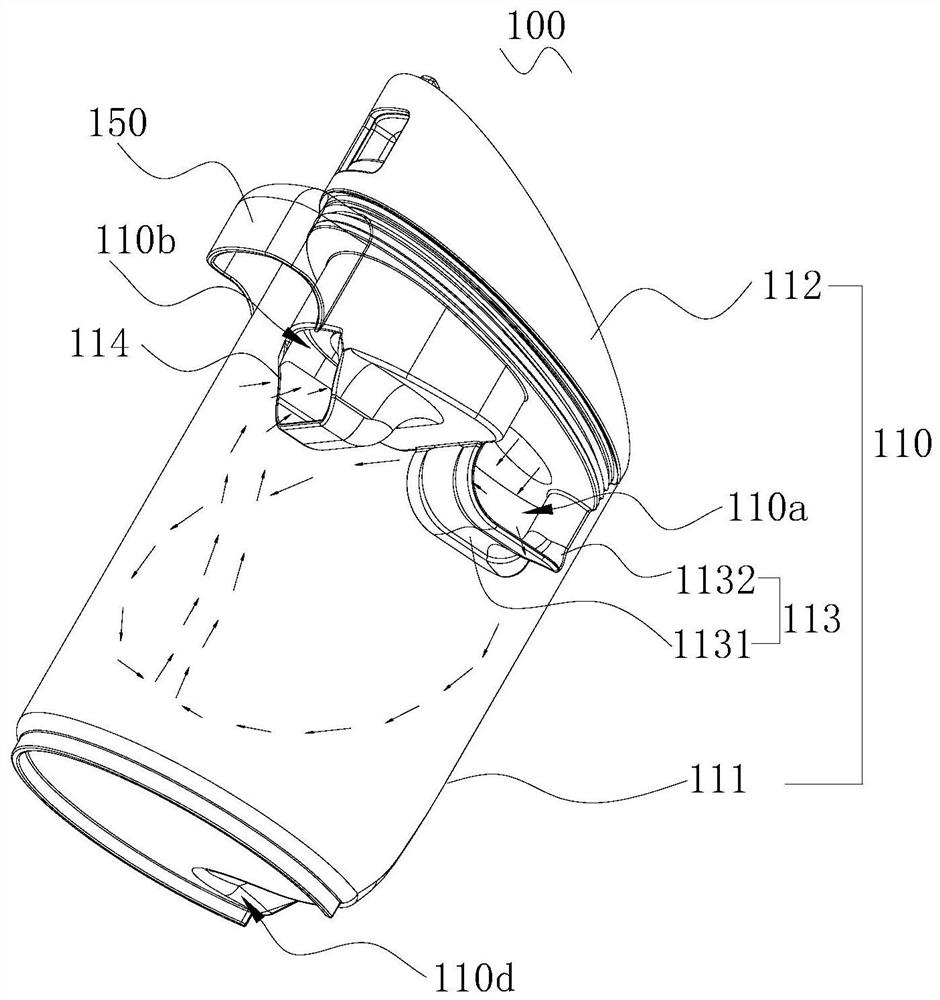
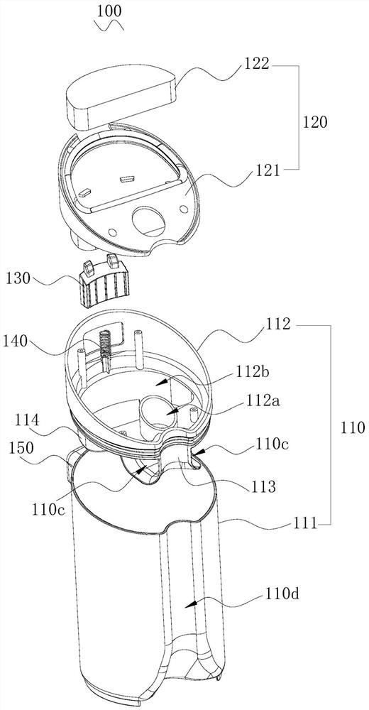
The invention relates to a sewage tank structure for cleaning equipment and the cleaning equipment. The sewage tank structure comprises a sewage tank, wherein the sewage tank is provided with a first flow channel and a second flow channel; the first flow channel is used for dividing fluid flowing into the sewage tank into a plurality of beams and enabling the plurality of beams of fluid to oppositely impact in the sewage tank; and the second flow channel is used for discharging gas in the sewage tank. After sewage garbage mixed with gas is divided into a plurality of bundles through the first flow channel, gas-liquid separation occurs in the process that each bundle of sewage garbage mixed with gas flows downwards into the sewage tank, and in the separation process, each bundle of sewage mixed with gas is subjected to opposite flushing in the sewage tank, so that the sewage garbage mixed with gas flows into the sewage tank; the kinetic energy of each beam of sewage mixed with gas is mutually reduced, counteracted or at least partially counteracted due to hedging, so that sewage garbage stably flows into the sewage tank, the separated gas and gas in other fluid beams are hedged in the sewage tank, the kinetic energy of the gas is reduced, and therefore, the suction generating device can more easily suck the separated gas through the second flow channel.

Description

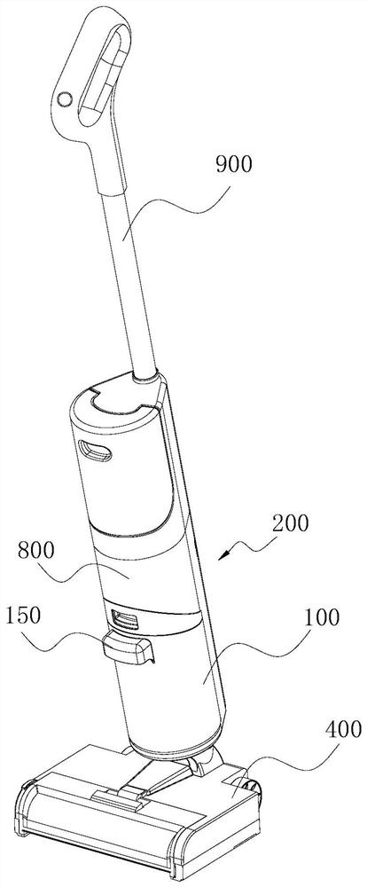
technical field [0001] The invention relates to the technical field of cleaning appliances, in particular to a sewage tank structure and cleaning equipment used for cleaning equipment. Background technique [0002] As one of the important parts of the wet vacuum cleaner, the sewage tank is mainly used to collect the inhaled sewage garbage. Wherein, the suction port of the existing sewage tank is usually set at the bottom of the sewage tank and is arranged as a columnar structure protruding to the interior of the sewage tank, which will cause the airflow in the sewage tank to easily stir the liquid, so that the sewage in the sewage tank is Inhalation into the motor will not only cause the motor to be easily damaged, but also the sewage will be blown to the outside of the wet vacuum cleaner. Contents of the invention [0003] Based on this, it is necessary to provide a sewage tank structure and cleaning equipment for cleaning equipment to solve the problem that the sewage g...

Claims


Application Information

Patent Timeline
Patent Type & Authority Applications(China)
IPC IPC(8): A47L7/00A47L9/00A47L9/10
CPCA47L7/0004A47L7/0023A47L9/00A47L9/102A47L5/30A47L11/4013A47L11/302
Inventor 吴航宇
Owner KEEWOO ROBOTICS TECH CO LTD
Why Eureka
Try Eureka