Waste gas treatment equipment for chemical engineering

A kind of exhaust gas treatment equipment and chemical technology, which is applied in chemical instruments and methods, separation of dispersed particles, filtration of dispersed particles, etc. It can solve the problems of slow filtration speed, failure to pass through the demister normally, and fast replacement speed of the demister.

Inactive Publication Date: 2021-05-11
陈娅雄
View PDF10 Cites 0 Cited by
  • Summary
  • Abstract
  • Description
  • Claims
  • Application Information

AI Technical Summary

Problems solved by technology

[0004] Aiming at the deficiencies of the existing technology, the purpose of the present invention is to provide a chemical waste gas treatment equipment to solve the problem in the prior art that when the tower type waste gas treatment equipment is used to treat the waste gas produced by the chemical fiber factory, due to the Contains more fiber impurities. When it is filtered layer by layer to the demister, the lower surface of the demister is more likely to have a large amount of waste than the upper part, resulting in the exhaust gas filtered from the lower part not passing through the demister normally. , resulting in a faster replacement speed of the demister and a slower filtration speed

Method used


Image

  • Waste gas treatment equipment for chemical engineering
  • Waste gas treatment equipment for chemical engineering
  • Waste gas treatment equipment for chemical engineering

Examples


no. 1 example

[0030] Such as Figure 1-Figure 6 As shown, the present invention provides a technical scheme of chemical waste gas treatment equipment:

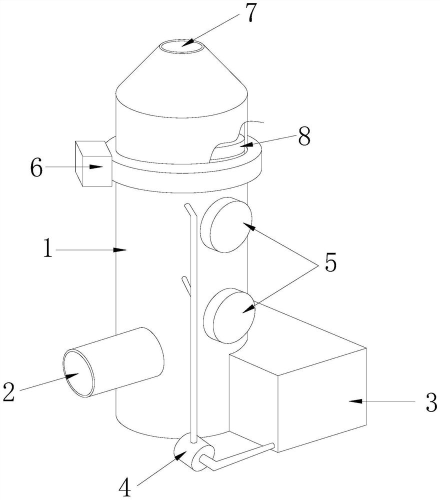
[0031] Such as Figure 1-Figure 2 As shown, a chemical waste gas treatment equipment, its structure includes a tank body 1, a waste gas inlet 2, a water tank 3, a water pump 4, a maintenance door 5, a gas channeling acceleration device 6, and a waste gas outlet 7. The waste gas inlet 2 is located at The lower part of the front surface of the tank body 1, the water tank 3 is arranged on and connected to the front surface of the tank body 1, one end of the water pump 4 is connected to the water tank 3, and the other end is connected to the tank body 1, and the maintenance door 5 is provided together There are two and are respectively installed on the front surface of the tank body 1, the gas channeling acceleration device 6 is arranged on the upper part of the tank body 1, and is located on the lower surface of the demister 8, and the waste ...

no. 2 example

[0042] Such as Figure 5-Figure 6 As shown, the present invention provides a technical scheme of chemical waste gas treatment equipment:

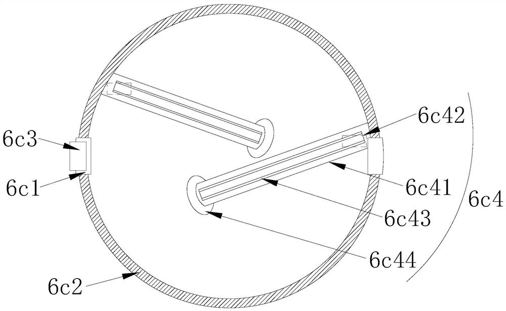
[0043] Such as Figure 5-Figure 6 As shown, a kind of waste gas treatment equipment for chemical industry, its structure includes the said buckle chamber 6d including a chamber 6d1, orbital ring 6d2, movable hole 6d3, sealing ring strip 6d4, said orbital ring 6d2 is provided with two and respectively It is installed in the inner upper part of the cavity 6d1 in a spaced shape, and the track ring 6d2 cooperates with the sliding buckle g3. The movable hole 6d3 is set in the middle of the upper surface of the cavity 6d1 and is an integrated structure. The sealing ring 6d4 There are two parallel structures installed inside the movable hole 6d3 respectively, which are beneficial to realize the movable movement of the sticking and scraping component 6c4 and collect waste materials.

[0044] Such as Figure 5-Figure 6 As shown, a suction pump is...


PUM


Abstract

The invention discloses waste gas treatment equipment for chemical engineering. The waste gas treatment equipment structurally comprises a tank body, a waste gas inlet, a water tank, a water pump, a maintenance door, a gas channeling acceleration device and a waste gas outlet. The equipment disclosed by the invention has the beneficial effects that a movable ring is electrified to rotate through an arranged stroking and scraping structure under the electrifying action of an induction electric box, two sticking and scraping assemblies are arranged in a crossed manner at an interval to rotationally scrape waste attached to the lower surface of a demister in the tank body in all directions, so that the situation that a large amount of waste is attached to the lower surface of the demister and then continuously upward filtered gas below cannot be effectively and smoothly filtered is prevented, and through cooperation of a buckle containing cavity and the stroking and scraping structure, waste impurities scraped by the stroking and scraping structure are effectively and intensively contained and therefore, the waste impurities are prevented from being attached to the lower surface of the demister again in the continuous scraping process of the stroking and scraping structure.

Description

technical field [0001] The invention relates to the field of waste gas treatment, more precisely, it is a chemical waste gas treatment equipment. Background technique [0002] Chemical fiber factories produce chemical fibers made from natural cellulose, protein and synthetic polymer compounds through a series of processes. During the production process, a large amount of harmful gas will be produced, so it needs to be processed with waste gas treatment equipment before it can be discharged into the air. [0003] When using tower-type waste gas treatment equipment to treat the waste gas produced by chemical fiber factories, because the gas contains more fiber impurities, when it is filtered layer by layer to the demister, the lower surface of the demister is relative to the upper part. , it is easier to have a large amount of waste materials, which causes the exhaust gas filtered from the lower part to fail to pass through the demister normally, resulting in a faster replace...

Claims


Application Information

Patent Timeline
IPC IPC(8): B01D46/00B01D46/24B01D46/48
CPCB01D46/2411B01D46/48B01D46/681
Inventor 林雪玲
Owner 陈娅雄
Why Eureka
Try Eureka