Dust and waste gas cleaning and dedusting system

A technology of dust removal system and waste gas, which is applied in the separation of dispersed particles, chemical instruments and methods, and filtration of dispersed particles, etc., can solve the problems of reducing the cleaning efficiency of waste gas, unable to replace the dust removal system of dust and waste gas, affecting normal cleaning and dust removal, etc.

Active Publication Date: 2021-09-14
SHENZHEN MEIPUDA ENVIRONMENTAL PROTECTION EQUIP CO LTD
View PDF8 Cites 4 Cited by
  • Summary
  • Abstract
  • Description
  • Claims
  • Application Information

AI Technical Summary

Problems solved by technology

[0003] However, there are still some deficiencies in the existing dust exhaust gas cleaning and dust removal system during use. The existing dust exhaust gas cleaning and dust removal system will block the filter plate inside the dust exhaust gas cleaning and dust removal system after the exhaust gas is dedusted for a long time , thereby reducing the efficiency of cleaning the exhaust gas, and the existing dust and exhaust gas cleaning and dust removal system is more troublesome when replacing the filter plate, and cannot quickly replace the filter inside the dust and exhaust gas cleaning and dust removal system, thus affecting the dust and exhaust gas cleaning and dust removal system. For the normal cleaning and dust removal of exhaust gas, at the same time, it is not convenient to control according to the flow rate inside, and the internal self-adaptive adjustment and control requirements cannot be realized. Therefore, a dust and exhaust gas cleaning and dust removal system is needed to solve the problems raised above.

Method used


Image

  • Dust and waste gas cleaning and dedusting system
  • Dust and waste gas cleaning and dedusting system
  • Dust and waste gas cleaning and dedusting system

Examples


Embodiment 1

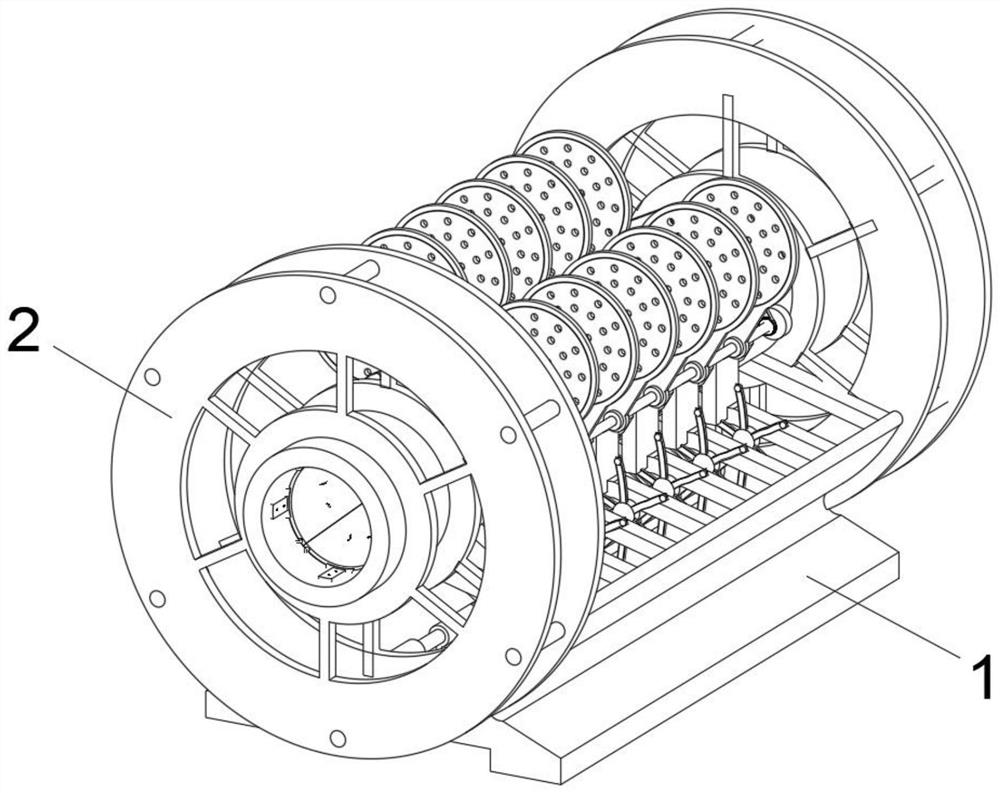
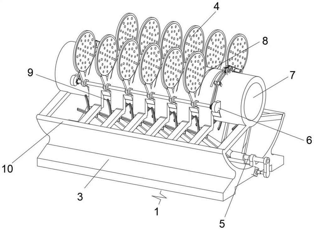
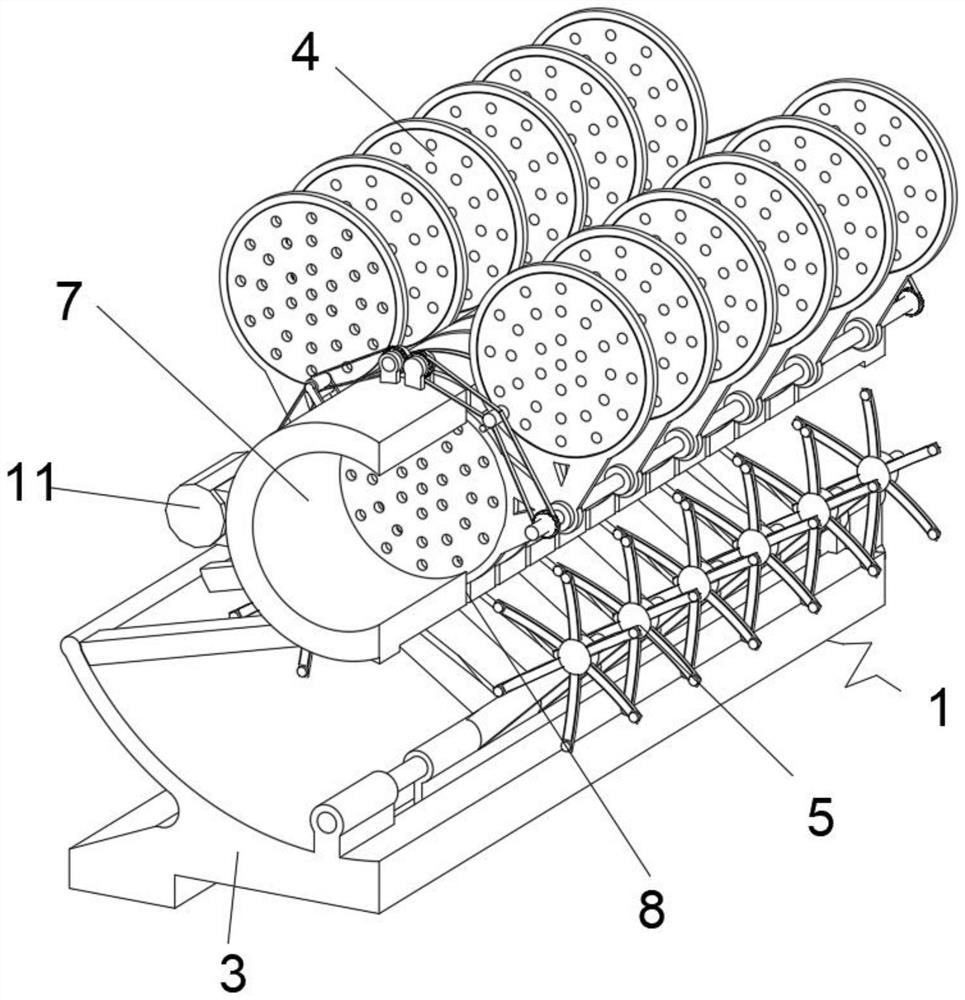
[0030] see Figure 1-7 , an embodiment provided by the present invention: a dust and waste gas cleaning and dedusting system, including a waste gas conveying device 1 and a waste gas flow control device 2, the waste gas flow control device 2 is fixedly installed on both ends of the waste gas conveying device 1, and the waste gas conveying device 1 The inside includes support seat 3, dust removal device 4, control device 5, bearing seat 6, exhaust gas pipe 7, socket slot 8, groove 9, arc plate 10 and drive motor 11, arc plate 10 is welded symmetrically on the support seat 3, the control device 5 is slidably installed on the center of the upper surface of the support base 3, the exhaust gas pipeline 7 is welded on the top surface center of the support base 3, and the bearing housing 6 is symmetrically welded on the outer surface of the two ends of the exhaust gas pipeline 7, plugged in Grooves 8 are evenly opened on the outer surface of the exhaust gas pipeline 7, the dust remov...

Embodiment 2

[0039] On the basis of Example 1, such as Figure 8 As shown, the inside of the support base 3 also includes a drainage groove 33 and a collecting plate 34. The drainage groove 33 is provided on both sides of the center of the upper surface of the support base 3.

[0040] During the implementation of this embodiment, the control device 5 will slide laterally to push and drop the used waste gas pipe 7 to the inside of the support seat 3, and the dust on the surface will fall when the filter plate 21 falls, so that the collecting plate 34 Collect the falling dust to prevent the dust from scattering and polluting the environment.

[0041] Working principle: When dedusting the exhaust gas, it is necessary to pass the exhaust gas into the interior of the exhaust gas pipeline 7, so that the exhaust gas passes through the filter plate 21 inside the exhaust gas pipeline 7, and the particles inside the exhaust gas are filtered to clean the exhaust gas. After filtering the exhaust gas ...


PUM


Abstract

The invention discloses a dust and waste gas cleaning and dedusting system which comprises a waste gas conveying device and waste gas flow control devices fixedly installed on the two end faces of the waste gas conveying device. The waste gas conveying device internally comprises a supporting base, a dust removal device, a control device, bearing pedestals, a waste gas pipeline, inserting grooves, a groove, arc-shaped plates and a driving motor, the arc-shaped plates are symmetrically welded to the two side faces of the supporting base, the control device is slidably mounted in the center of the upper surface of the supporting base, and the waste gas pipeline is welded to the center of the top surface of the supporting base; the bearing pedestals are symmetrically welded to the outer surfaces of the edges of the two ends of the waste gas pipeline, and the inserting grooves are evenly formed in the outer surface of the waste gas pipeline. Through rotation control of the dust removal device, the filter plate in the waste gas pipeline can be quickly replaced, so that the shutdown time of the waste gas conveying device is prolonged, and unqualified dust removal of waste gas is prevented.

Description

technical field [0001] The invention relates to the technical field of waste gas and dust removal equipment, in particular to a dust waste gas cleaning and dust removal system. Background technique [0002] Exhaust gas purification mainly refers to the treatment of industrial waste gas generated in industrial places, such as dust particles, flue gas, odorous gas, and toxic and harmful gases. Common exhaust gas purification includes factory smoke and dust exhaust gas purification, workshop dust exhaust gas purification, and organic waste gas purification. , acid and alkali waste gas purification, chemical waste gas purification and odor deodorization purification, etc. When the waste gas is cleaned and purified, it is necessary to use the dust waste gas cleaning and dust removal system to clean the waste gas so that the waste gas can reach the qualified standard for discharge. [0003] However, there are still some deficiencies in the existing dust exhaust gas cleaning and du...

Claims


Application Information

Patent Timeline
Patent Type & Authority Applications(China)
IPC IPC(8): B01D46/12B01D46/00B01D46/48
CPCB01D46/12B01D46/0005B01D46/48
Inventor 张善平
Owner SHENZHEN MEIPUDA ENVIRONMENTAL PROTECTION EQUIP CO LTD
Why Eureka
Try Eureka