
Horizontal spiral discharging and filtering centrifugal machine convenient to discharge

A horizontal screw and centrifuge technology, which is applied to centrifuges, centrifuges with rotating drums, mechanical equipment, etc., can solve the problems of inconvenient unloading of solid materials and increased humidity, so as to improve practicability and reduce wasteful effect

Pending Publication Date: 2021-05-11
江苏图胜离心机制造有限公司
View PDF0 Cites 3 Cited by
  • Summary
  • Abstract
  • Description
  • Claims
  • Application Information

AI Technical Summary

Problems solved by technology

[0003] The horizontal spiral discharge filter centrifuge is a kind of centrifuge. When the existing horizontal spiral discharge filter centrifuge is discharging, it is inconvenient to discharge solid materials, and the existing horizontal spiral discharge filter During the use of the centrifuge, a certain amount of liquid will be thrown into the solid discharge pipe after passing through the drum, which will cause the dehydrated material in the solid discharge pipe to increase a certain humidity again.

Method used


Image

  • Horizontal spiral discharging and filtering centrifugal machine convenient to discharge
  • Horizontal spiral discharging and filtering centrifugal machine convenient to discharge
  • Horizontal spiral discharging and filtering centrifugal machine convenient to discharge

Examples


Embodiment

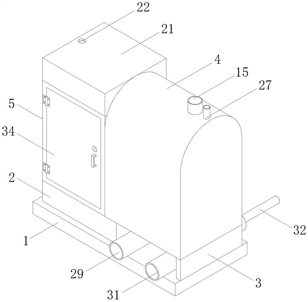
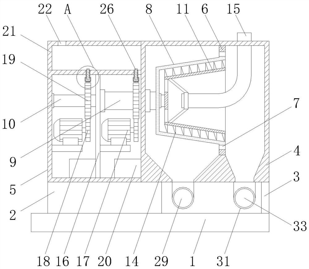
[0029] Example: such as Figure 1-6 , a horizontal spiral discharge filter centrifuge that is convenient for unloading according to the present invention includes a base 1, a pad 2 and a support block 3 on the right side of the pad 2 are fixedly installed on the top of the base 1, and the top of the pad 2 is fixed A protective box 5 is installed, and the top of the support block 3 is fixedly equipped with a centrifugal chamber 4, and the left side of the centrifugal chamber 4 is fixedly connected with the right side of the protective box 5, and the front of the protective box 5 is hinged with a protective door 27 through a hinge. Locks and handles are provided on the door 27;

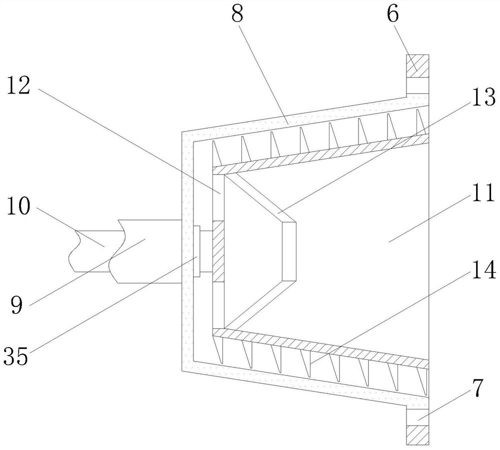
[0030] A centrifugal assembly is arranged between the centrifugal chamber 4 and the protective box 5, and the centrifugal assembly consists of a partition plate 6, a first sealed bearing 7, a drum 8, a rotating shaft 9, a rotating tube 10, an inner cylinder 11, two It is composed of feed port 12, a pro...


PUM


Abstract

The invention discloses a horizontal spiral discharging and filtering centrifugal machine convenient to discharge. The machine comprises a base, a cushion block and a supporting block located on the right side of the cushion block are fixedly installed at the top of the base, a protection box is fixedly installed at the top of the cushion block, a centrifugal chamber is fixedly installed at the top of the supporting block, and the left side face of the centrifugal chamber is fixedly connected with the right side face of the protection box. According to the machine, after solid materials fall into a solid discharge pipe and a discharging pipe from the centrifugal chamber, the solid materials in the discharging pipe can be pushed out by pushing a pushing block through a hydraulic cylinder, and therefore discharging of the horizontal spiral discharging and filtering centrifugal machine is facilitated; and two motors, two driving wheels and two driven wheels are matched with one another to drive a rotating pipe and a rotating shaft to rotate, the rotating pipe and the rotating shaft can drive a rotating drum and an inner barrel to rotate in different rotating directions, and therefore the inner barrel can drive outer spiral parts to accelerate discharging of solids attached to the inner wall of the rotating drum, and the practicability of the spiral discharging and filtering centrifugal machine is further improved.

Description

technical field [0001] The invention relates to a horizontal spiral discharge filter centrifuge, in particular to a horizontal spiral discharge filter centrifuge which is convenient for discharge. Background technique [0002] A centrifuge is a machine that uses centrifugal force to separate components in a mixture of liquid and solid particles or liquid and liquid. The centrifuge is mainly used to separate the solid particles in the suspension from the liquid, or to separate the two densities in the emulsion. , and separate immiscible liquids, using the characteristics of different sedimentation speeds of solid particles of different densities or particle sizes in liquids, some sedimentation centrifuges can also classify solid particles according to density or particle size, centrifuges are widely used in chemical industry , Petroleum, food, pharmaceuticals, mineral processing, coal, water treatment and ships and other sectors. [0003] The horizontal spiral discharge filt...

Claims


Application Information

Patent Timeline
Patent Type & Authority Applications(China)
IPC IPC(8): B04B11/04B04B1/20B04B15/00B04B7/08F16N11/06
CPCB04B1/20B04B1/2016B04B7/08B04B11/04B04B15/00F16N11/06
Inventor 林宏洪徐建林子涛姚佳喜
Owner 江苏图胜离心机制造有限公司
Learn More