

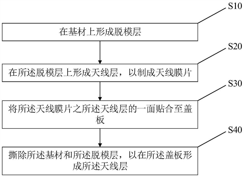
Manufacturing method of antenna cover plate and electronic equipment
A manufacturing method and antenna cover technology, which is applied to antennas, electronic equipment, antenna parts, etc., can solve the problems of low yield rate of antenna cover plates
- Summary
- Abstract
- Description
- Claims
- Application Information
AI Technical Summary
Problems solved by technology
Method used
Image

Examples
Embodiment Construction
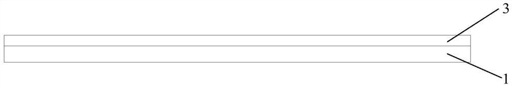
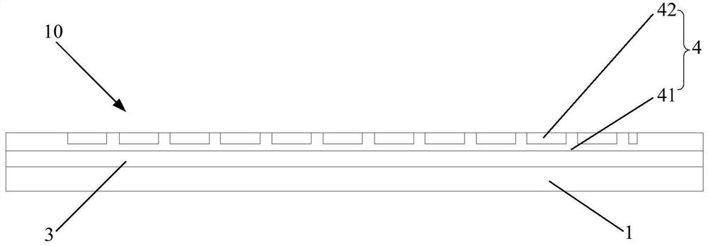
[0046] The following will clearly and completely describe the technical solutions in the embodiments of the present invention in conjunction with the accompanying drawings in the specific embodiments of the present invention. Obviously, the described embodiments are only part of the embodiments of the present invention, not all of them. . Based on the embodiments of the present invention, all other embodiments obtained by persons of ordinary skill in the art without creative efforts fall within the protection scope of the present invention.
[0047] At present, antenna design of electronic products is based on flexible printed circuit (FPC) and laser direct structuring (LDS) technology. With the increasing proportion of full-screen screens and the arrival of 5G, there are more and more requirements for the location and area of antennas. The antenna design on the top and bottom of the conventional screen cannot meet the structural design requirements of electronic products. ...
PUM
 Abstract
Description
Claims
Application Information