
Oil-gas-water three-phase multi-stage separation device in oil extraction shaft

A multi-stage separation and gas-phase separation technology is applied in the field of oil-gas-water three-phase multi-stage separation devices in oil production wellbore, which can solve the problems such as fluctuation of intake air volume.

Active Publication Date: 2021-05-11
NORTHEAST GASOLINEEUM UNIV
View PDF8 Cites 4 Cited by
  • Summary
  • Abstract
  • Description
  • Claims
  • Application Information

AI Technical Summary

Problems solved by technology

[0003] The invention provides an oil-gas-water three-phase multi-stage separation device in an oil production wellbore. According to the different density differences between the phases, the device first discharges the gas phase with the lowest density to eliminate the adverse effects on oil-water separation, and then realizes Oil-water separation, aiming at the problem of different gas content in different oil wells and the fluctuation of intake air volume in the same oil well separation process, a control module is designed to accurately remove the gas phase entering the device, and then perform cyclone separation, and after oil-water separation Realize the re-injection of the water phase downhole, not only achieve accurate degassing, but also have good applicability to different gas-containing media, and can ensure the purity of the oil phase separation, and have a strong ability to separate the oil phase of the downhole production fluid

Method used


Image

  • Oil-gas-water three-phase multi-stage separation device in oil extraction shaft
  • Oil-gas-water three-phase multi-stage separation device in oil extraction shaft
  • Oil-gas-water three-phase multi-stage separation device in oil extraction shaft

Examples


Embodiment Construction

[0057] The present invention will be further described below in conjunction with accompanying drawing:

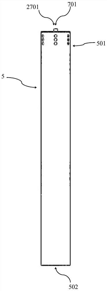
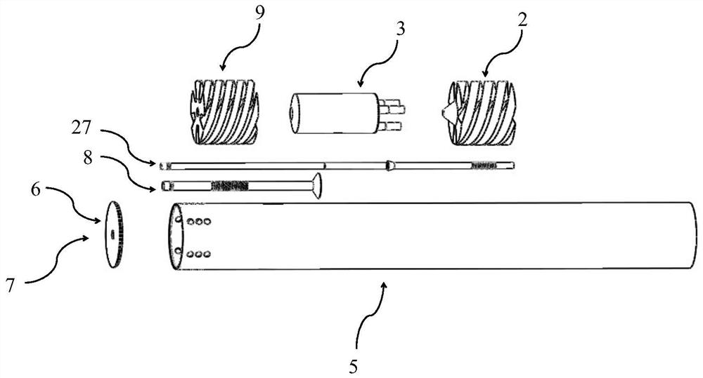
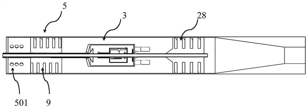
[0058] The overall appearance of the oil-gas-water three-phase multi-stage separation device in the oil production wellbore is as follows figure 1 As shown, the gas-liquid-solid three-phase mixed liquid enters the outer sleeve 5 from the mixed medium inlet 501 for separation, the gas phase is discharged through the vent hole 701 , the oil phase is discharged through the oil phase outlet 2701 , and the underflow liquid is discharged through the underflow port 502 . The explosion diagram of the oil-gas-water three-phase multi-stage separation device in the oil production wellbore is as follows figure 2 As shown, the device is mainly composed of an outer sleeve 5, an overflow head 6, an exhaust hole plate 7, an exhaust pipe 8, a primary spiral flow channel 9, a control module 3, an oil discharge pipe 27, and a secondary spiral flow channel 28 composition. image 3 It is a c...


PUM


Abstract

The invention discloses an oil-gas-water three-phase multi-stage separation device in an oil extraction shaft. The oil-gas-water three-phase multi-stage separation device in the oil extraction shaft is characterized that the device comprises a device shell, a gas-phase separation module, a control module and a liquid-phase separation module, after gas-liquid-solid three-phase mixed liquid enters a cyclone separator from a mixed medium inlet of an outer sleeve, a gas phase is preferentially discharged after passing through the gas-phase separation module, and an oil phase entering an oil-gas storage cavity together with the gas phase flows back into the outer sleeve after passing through the control module and an anti-backflow device and is mixed with other oil phases and a water phase outside the storage cavity, so that separation of the water phase and the oil phase is achieved through the liquid-phase separation module, the water phase is discharged from an underflow port, and the oil phase is discharged from an oil phase overflow pipe. The oil-gas-water three-phase multi-stage separation device can be applied to under the shaft, high-efficiency degassing is achieved before oil-water separation, and the adverse effect on cyclone separation caused by the existence of the gas phase is avoided.

Description

technical field [0001] The invention relates to a device for pre-separation of oil medium in wells and three-phase cyclone separation of oil, gas and water. Background technique [0002] In the process of oil field production, oilfield associated gas exists in the downhole production medium, and the gas phase, as a light phase, has a serious adverse effect on the oil-water separation process. During the cyclone separation process, the gas phase will Gather at the center of the fluid to form gas nuclei. The existence of gas nuclei seriously affects the oil-water separation efficiency of the downhole cyclone. Although the existing downhole separation devices can achieve degassing, they are not very good for oil wells with different gas contents. Applicability, or during the production of the same oil well, the fluctuation of the air intake will reduce the downhole oil-water separation efficiency. At the same time, with the continuous production of the oil field, it is necessar...

Claims


Application Information

Patent Timeline
IPC IPC(8): E21B43/38E21B43/40B01D17/02B01D19/00
CPCE21B43/385B01D17/0217B01D17/02B01D19/0052
Inventor 邢雷李枫赵立新刘海龙李金煜郑九洲
Owner NORTHEAST GASOLINEEUM UNIV
Learn More