Schmitt trigger circuit with input buffer circuit
A Schmitt trigger and input buffer circuit technology, applied in the components, pulse technology, pulse generation and other directions of generating electrical pulse circuits, can solve problems such as chip damage, inability to use high-voltage analog signal input, etc., to ensure correctness , the effect of extending the application
- Summary
- Abstract
- Description
- Claims
- Application Information
AI Technical Summary
Problems solved by technology
Method used
Image
Examples
Embodiment Construction
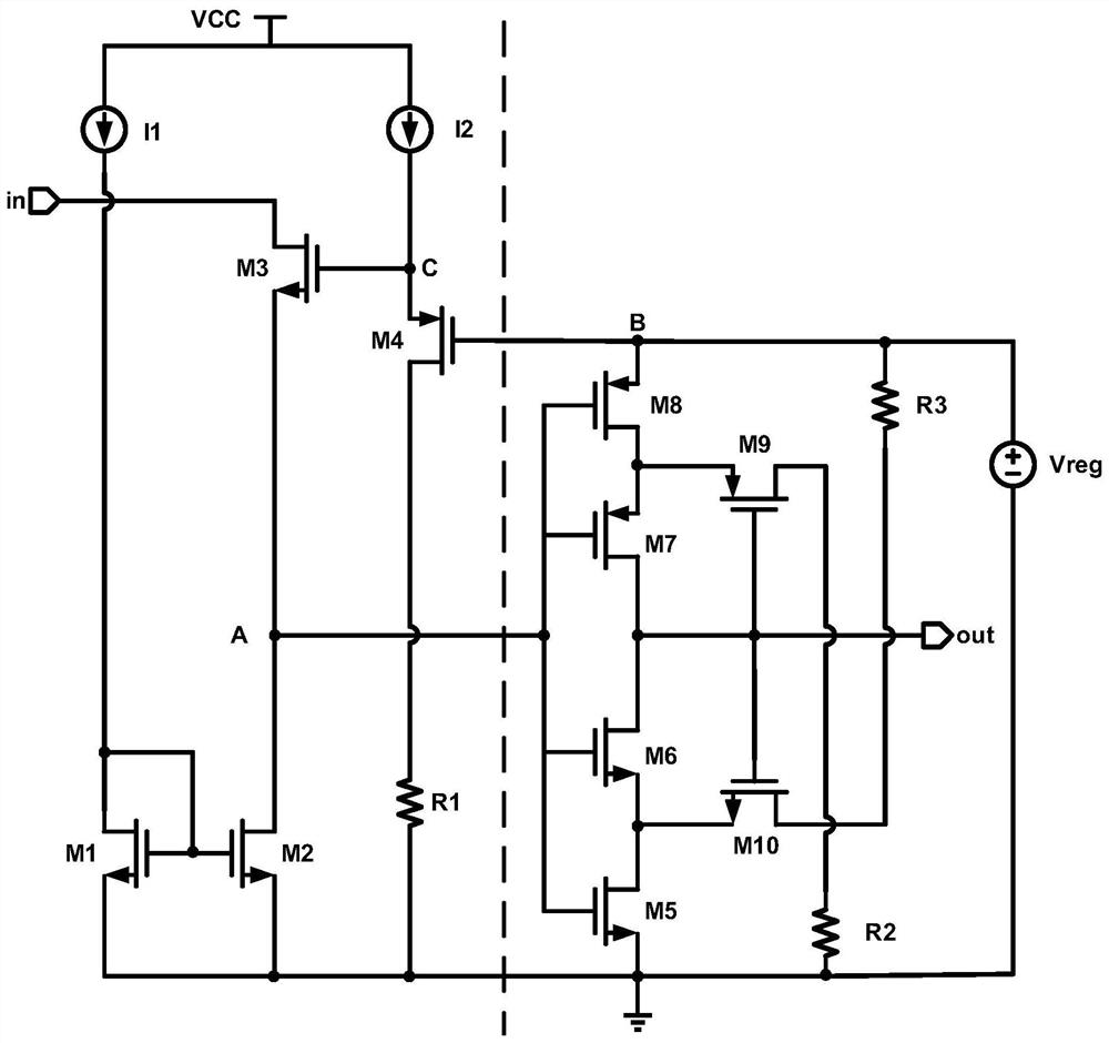
[0016]Below with the accompanying drawings (Figure 1 - Figure 2 The present invention will be described.
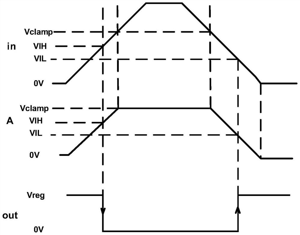
[0017]figure 1 It is a schematic structural diagram of a Schmitt trigger circuit with an input buffer circuit.figure 2 Yesfigure 1 Node voltage waveform diagram. Such asFigure 1 to 2As shown, a Schmidt trigger circuit having an input buffer circuit includes an input buffer circuit (for example,figure 1 The left side of the middle vertical dashed line) and the low voltage Schmitt trigger circuit (for example,figure 1 On the right side of the intermediate vertical dashed line), the input buffer circuit is connected to the low voltage input node of the low-voltage Schmitt trigger circuit by the clamp voltage node A. The input buffer circuit includes a third NMOS tube M3, a drain connection of the third NMOS tube M3 connected to an analog signal input terminal IN, and the source of the third NMOS tube M3 passes through the clamp voltage node A. The drain of the NMOS tube M2, the sourc...
PUM
 Abstract
Description
Claims
Application Information
 - R&D
- Intellectual Property
- Life Sciences
- Materials
- Tech Scout
- Unparalleled Data Quality
- Higher Quality Content
- 60% Fewer Hallucinations
Browse by: Latest US Patents, China's latest patents, Technical Efficacy Thesaurus, Application Domain, Technology Topic, Popular Technical Reports.
© 2025 PatSnap. All rights reserved.Legal|Privacy policy|Modern Slavery Act Transparency Statement|Sitemap|About US| Contact US: help@patsnap.com


