
Wall-mounted electrical control cabinet

A technology for electrical control cabinets and electrical appliances, which is applied to electrical components, electrical equipment shells/cabinets/drawers, casings/cabinets/drawer parts, etc., and can solve the problems of inability to quickly change positions and inability to change positions at will , to achieve the effect of stable structure, not easy to fall off, and high connection strength

Inactive Publication Date: 2021-05-11
XIAN RENKE ELECTRONICS TECH CO LTD
View PDF0 Cites 0 Cited by
  • Summary
  • Abstract
  • Description
  • Claims
  • Application Information

AI Technical Summary

Problems solved by technology

[0004] The purpose of the present invention is to provide a wall-mounted electrical control cabinet to solve the problem that the wiring position of the electrical control cabinets on the market proposed in the above background technology is mostly fixed during use, and the position cannot be changed quickly, and the installation position of electronic components Most of them are fixed, and the problem that you can't change the position at will according to your own needs

Method used


Image

  • Wall-mounted electrical control cabinet
  • Wall-mounted electrical control cabinet
  • Wall-mounted electrical control cabinet

Examples


Embodiment Construction

[0020] The following will clearly and completely describe the technical solutions in the embodiments of the present invention with reference to the accompanying drawings in the embodiments of the present invention. Obviously, the described embodiments are only some, not all, embodiments of the present invention. Based on the embodiments of the present invention, all other embodiments obtained by persons of ordinary skill in the art without making creative efforts belong to the protection scope of the present invention.

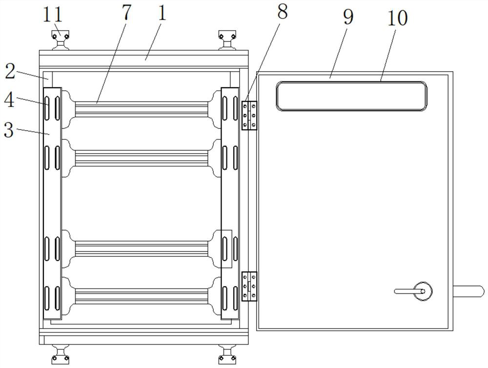
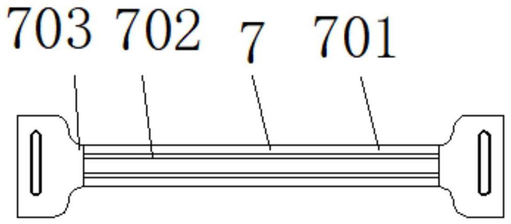
[0021] see Figure 1-4 , the present invention provides a technical solution: a wall-mounted electrical control cabinet, including a body 1, an inner hanging plate 2, a fixing plate 3, a waist tight hole 4, a connecting groove 5, a gasket 6, an electrical installation structure 7, and an electrical installation plate 701, trunking 702, side mounting plate 703, hinge 8, box door 9, window 10 and wall hanging piece 11, the inner wall both sides of body 1 are fix...


PUM


Abstract

The present invention discloses a wall-mounted electrical control cabinet which comprises a machine body and waist tightening holes, inner hanging plates are fixed to the two sides of the inner wall of the machine body, fixing plates are fixed to the outer walls of the inner hanging plates, the waist tightening holes are formed in the two sides of the middles of the fixing plates, connecting grooves are formed in the middles of the inner sides of the fixing plates, and sealing gaskets are attached to the inner walls of the connecting grooves. Electric appliance mounting structures are distributed on the inner wall of the connecting groove, and hinges are distributed on one side of the outer wall of the machine body. The wall-mounted electric control cabinet is provided with the fixing plate, the fixing plate and the inner hanging plate are of a detachable structure, the whole fixing plate and the inner hanging plate serve as a basic fixing structure of an electric appliance installation structure and are fixed together through screws, and the waist tightening holes are evenly distributed in the two sides of the fixing plate and the inner hanging plate. After the waist tightening holes between the fixing plate and the inner hanging plate coincide, a user can fix the fixing plate and the inner hanging plate through fixing parts such as screws, and the waist tightening holes are adopted as fixing connecting holes, so that various fixing modes of the user can be met.

Description

technical field [0001] The invention relates to the technical field of electrical control cabinets, in particular to a wall-mounted electrical control cabinet. Background technique [0002] The control cabinet is to assemble the switchgear, measuring instrument, protective device and auxiliary equipment in the closed or semiclosed metal cabinet or on the screen width according to the requirements of electrical wiring. and the safety of surrounding equipment. During normal operation, the circuit can be connected or disconnected by means of a manual or automatic switch. Cut off the circuit or alarm with the help of protective electrical appliances in case of failure or abnormal operation. Various parameters in operation can be displayed by means of measuring instruments, and some electrical parameters can also be adjusted to prompt or send out signals for deviations from normal working conditions. [0003] The position of the electrical control cabinets on the market is mos...

Claims


Application Information

Patent Timeline
Patent Type & Authority Applications(China)
IPC IPC(8): H05K5/02
CPCH05K5/0217
Inventor 梁兴辉
Owner XIAN RENKE ELECTRONICS TECH CO LTD
Learn More