Defoaming chemical reaction tank

A chemical reaction and tank technology, applied in the field of defoaming chemical reaction tanks, can solve problems such as poor defoaming effect and residual toxic substances

Inactive Publication Date: 2021-05-14
重庆市佰恒科技有限公司
View PDF0 Cites 4 Cited by
  • Summary
  • Abstract
  • Description
  • Claims
  • Application Information

AI Technical Summary

Problems solved by technology

[0004] Aiming at the problems of poor defoaming effect and residual toxic substances in the existing chemical

Method used


Image

  • Defoaming chemical reaction tank
  • Defoaming chemical reaction tank
  • Defoaming chemical reaction tank

Examples


Embodiment Construction

[0028] Embodiments of the technical solutions of the present invention will be described in detail below in conjunction with the accompanying drawings. The following examples are only used to illustrate the technical solutions of the present invention more clearly, and therefore are only examples, rather than limiting the protection scope of the present invention.

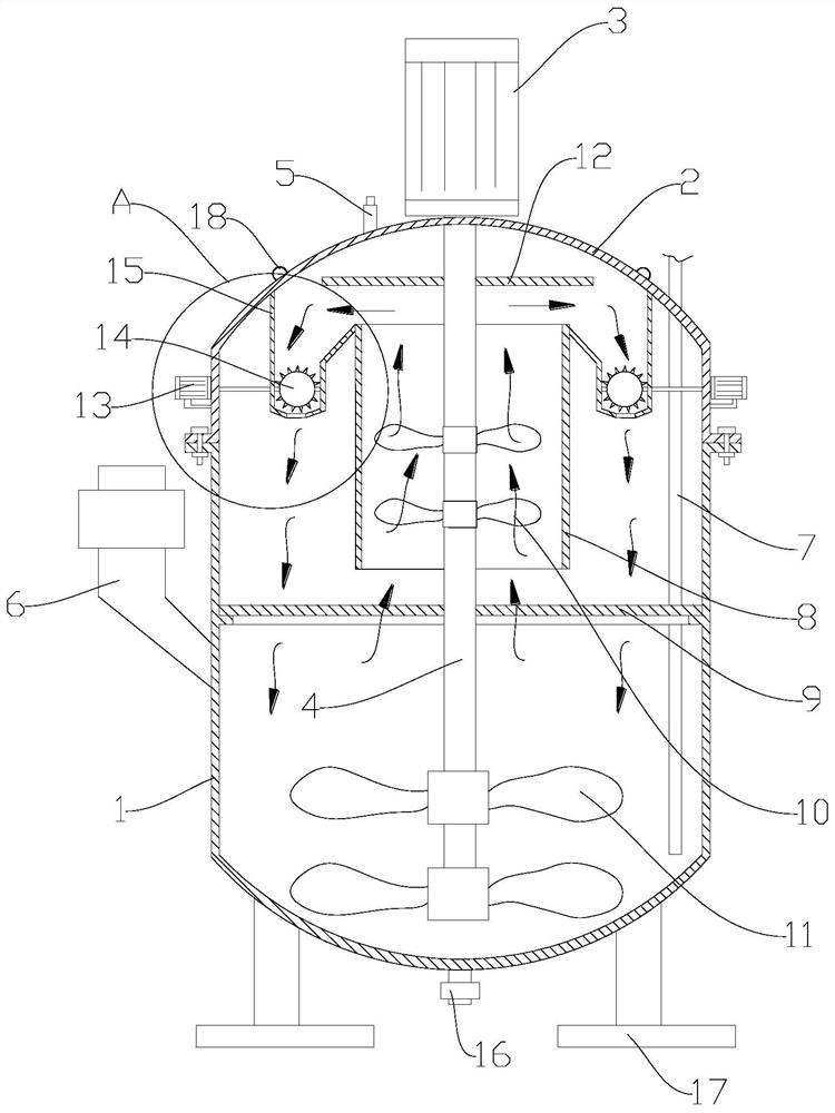
[0029] Such as figure 1 , a defoaming chemical reaction tank, the tank body includes a tank body 1 and a tank cover 2, the junction of the tank body 1 and the tank cover 2 is fixed with bolts, in order to prevent air leakage, a rubber pad is arranged between the joint surfaces, the tank Body 1 and can lid 2 form a closed space.

[0030] The chemical tank has a stirring device, the stirring device includes a first motor 3, a rotating shaft 4, a stirring blade 11 and a suction blade 10, the first motor 3 is fixed on the upper middle position of the tank cover 2, the rotating shaft 4 is located in the tank, and the r...


PUM


Abstract

The invention provides a defoaming chemical reaction tank. The reaction tank comprises a tank body, a stirring device, a guide cylinder, a backflow tank and a foam throwing plate, the stirring device comprises a rotating shaft and stirring blades and suction blades arranged on the rotating shaft, the upper end and the lower end of the guide cylinder are open, and the suction blades are located in the guide cylinder. The backflow tank is connected with a tank cover, the guide cylinder is connected with the backflow tank, a backflow opening is formed in the bottom of the backflow tank, and a foam breaking ball is arranged above the backflow opening, so that foam circulation flow is formed in the upper part of the tank body, most of foam is broken in the circulation movement, and the defoaming effect is further enhanced through a foam throwing plate and a foam breaking ball which are arranged in the circulating passage. The mechanical bubble removing mechanism is adopted, so that a good bubble removing effect is achieved, no harmful substance is left, and the problem of bacterial contamination caused by gas backflow is solved.

Description

technical field [0001] The invention relates to the technical field of chemical equipment, in particular to a defoaming chemical reaction tank. Background technique [0002] The chemical reaction tank is a device used in the chemical industry. During the fermentation process of the material placed in the tank, with the continuous growth, reproduction and metabolism of microorganisms, a certain amount of heat will be generated and a large amount of foam will be formed. Causes the risk of bacterial contamination; a large amount of foam also seriously affects the fermentation process, making the fermentation period longer and insufficient fermentation. [0003] Part of the defoaming effect can also be achieved by adding a defoamer to the tank. The commonly used defoamers mainly include polyethers and silicones. There will be residues, and the defoamer is expensive, and a large amount of use will increase production costs. The existing mechanical defoaming methods generally h...

Claims


Application Information

Patent Timeline
IPC IPC(8): B01J19/18B01D19/00
CPCB01D19/0031B01D19/0052B01J19/0053B01J19/0066B01J19/18
Inventor 张毅
Owner 重庆市佰恒科技有限公司
Why Eureka
Try Eureka