
Cutting device used for ampoule bottle dispensing robot

A technology for dispensing robots and cutting devices, which is applied in medical containers, drug packaging, electric operating devices, etc., and can solve problems such as failure to open bottles, large overall appearance of dispensing devices, and cumbersome dispensing process, etc.

Active Publication Date: 2020-07-28
深圳市博为医疗机器人有限公司
View PDF13 Cites 6 Cited by
  • Summary
  • Abstract
  • Description
  • Claims
  • Application Information

AI Technical Summary

Problems solved by technology

The dispensing device of the above technical solution has a large overall appearance, and the dispensing process is cumbersome, and only one ampoule bottle can be opened in each working cycle. This process takes a long time, which is not conducive to the centralized dispensing process; During the dispensing process of ampoules, the position of ampoules cannot be unified, resulting in different cutting depths, which in turn leads to the risk of bottle opening failure

Method used


Image

  • Cutting device used for ampoule bottle dispensing robot
  • Cutting device used for ampoule bottle dispensing robot
  • Cutting device used for ampoule bottle dispensing robot

Examples


Embodiment 1

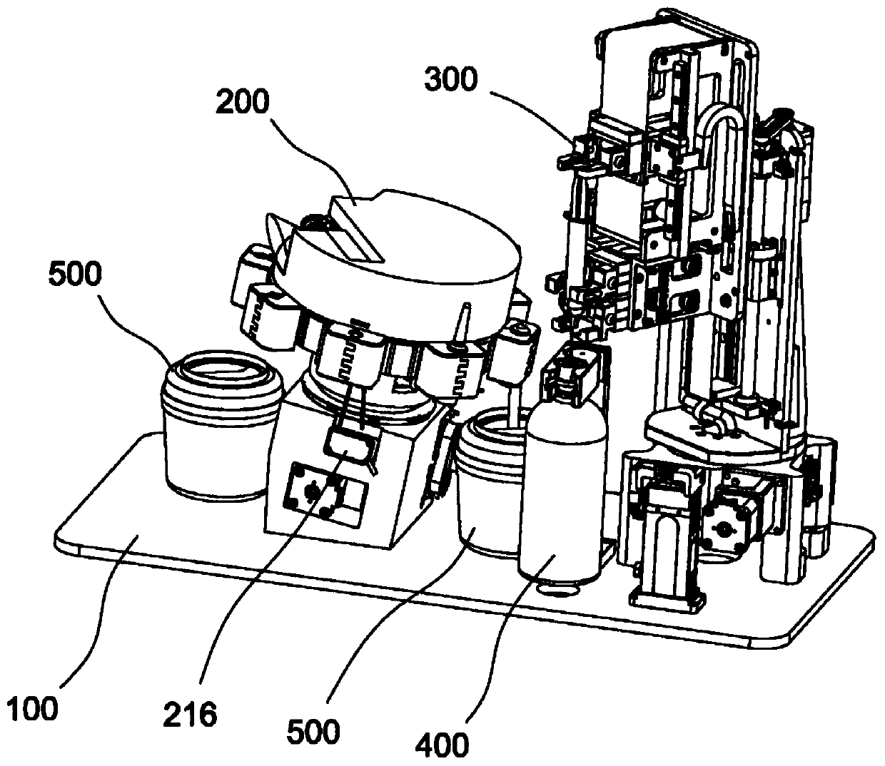
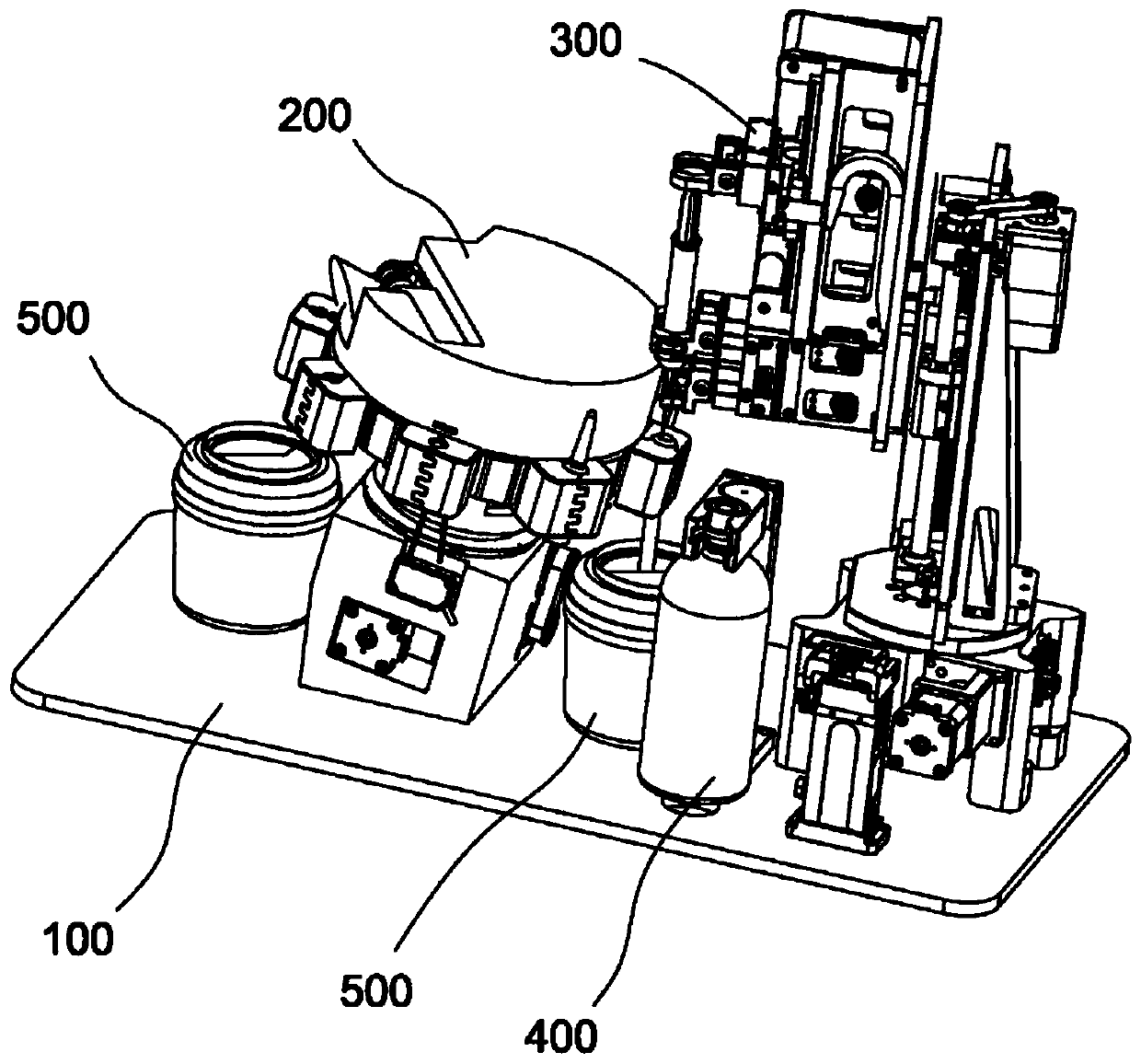
[0065] Such as figure 1 As shown in -10, this embodiment provides an automatic dispensing robot for ampoules, including a base 100, an automatic bottle opening device 200, a pipetting device 300, a solvent holding device 400 and a sharps collection device 500; wherein, the automatic The bottle opening device 200, the pipetting device 300, the solvent holding device 400 and the sharps collecting device 500 are all arranged on the base 100; in order to facilitate the automatic dispensing process, a preferred distribution is as follows: figure 1 , figure 2 As shown, the medium holding device 400 is disposed between the automatic bottle opening device 200 and the pipetting device 300 .

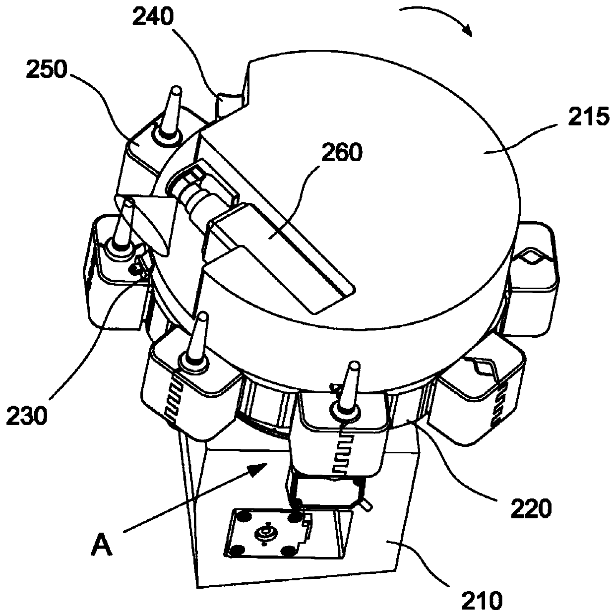
[0066] see image 3 , Figure 4 , the automatic bottle opening device 200 includes a storage table 210, a rotating medicine tray 220, a cutting mechanism 230 and a breaking mechanism 240. There are a plurality of clamping mechanisms 250 for clamping ampoules, preferably, eight clamping mechan...

Embodiment 2

[0104] Such as Figure 11 As shown, the difference between this embodiment and Embodiment 1 lies in that the peristaltic pump mechanism is used as the suction and injection mechanism in the pipetting device.

[0105] see Figure 11 , the pipetting device 600 includes a horizontal rotation mechanism 610 , a needle clamping mechanism 620 , a needle lifting mechanism 630 and a peristaltic pump mechanism 640 .

[0106] Among them, the settings of the horizontal rotation mechanism 610 and the needle lifting mechanism 630 are basically the same as those in Embodiment 1, and will not be repeated here.

[0107] The needle clamping mechanism 620 includes a clamping plate 621 fixed on the needle lifting mechanism 630 (lifting plate 631 ), and the end of the clamping plate 621 is provided with a through hole for the liquid suction needle 622 to pass through and be fixed.

[0108] The peristaltic pump mechanism 640 includes a peristaltic pump 641 fixed on the lifting plate 631. The peri...


PUM


Abstract

The invention provides a cutting device used for an ampoule bottle dispensing robot. The cutting device comprises a storage table, a rotating medicine disc, a cutting mechanism used for cutting an ampoule bottle opening, and a power mechanism used for controlling a knife wheel driving part to drive a cutter wheel to rotate by an angle, the periphery of the rotating medicine disc is provided with multiple clamping mechanisms used for clamping ampoule bottles, the ampoule bottles clamped by the clamping mechanisms synchronously rotate along with the rotating medicine disc, the cutting mechanismcomprises the knife wheel, a knife rest and the knife wheel driving part, the middle of the knife rest is rotatably mounted on the storage table through a knife rest shaft, the knife wheel is locatedon the work end of the knife rest, the knife wheel driving part is located on the free end of the knife rest, the driving part can drive the knife rest to rotate around the knife rest shaft to adjustthe position of the knife wheel, the power mechanism drives the knife wheel to be located on the rotating path of the ampoule bottles clamped by the clamping mechanisms, in the rotating process of theampoule bottles, the knife wheel makes contact with the ampoule bottles to cut the necks of the ampoule bottles, the cutting device is compact in structure, and the dispensing process of the ampoulebottles can be automatically finished.

Description

[0001] Divisional statement [0002] This application is a divisional application of the Chinese patent application with the application number 201811438209.0 and the title of the invention "An automatic dispensing robot for ampoules" submitted on November 28, 2018. technical field [0003] The invention belongs to the technical field of medical equipment, and more specifically relates to an automatic dispensing robot for ampoule bottles. Background technique [0004] The ampoule bottle is a small glass container used to hold medicines. Its structure includes a bottle body and a bottle head, as well as a bottleneck located in the concave part between the bottle body and the bottle head. The capacity is generally 1-25ml. The inside of the ampoule bottle is generally stored for injection drugs used. At present, the preparation of intravenous infusion drugs in hospitals is generally done manually, which is likely to cause drug pollution and harm to patients. At the same time, ...

Claims


Application Information

Patent Timeline
Patent Type & Authority Applications(China)
IPC IPC(8): B67B7/92A61J1/20B25J11/00B65F1/14
CPCA61J1/2003A61J1/2096A61J2200/70B67B7/38B67B7/92B65F1/14B25J11/00Y02P40/57
Inventor 崔杰王瑞强靳海洋
Owner 深圳市博为医疗机器人有限公司
Learn More