
Efficient and energy-saving extraction tank

A high-efficiency, energy-saving, extraction tank technology, applied in solid solvent extraction, chemical instruments and methods, solvent extraction, etc., can solve the problems of small capacity of appliances, energy consumption and man-hours, limited scope of action, etc., to improve efficiency and reduce operation. Cost, energy saving and man-hour effect

Inactive Publication Date: 2018-12-21
李肥生
View PDF4 Cites 5 Cited by
  • Summary
  • Abstract
  • Description
  • Claims
  • Application Information

AI Technical Summary

Problems solved by technology

At present, traditional extraction methods such as maceration, infiltration, and decoction are still widely used. Although some emerging new technology methods such as microwave method and ultrasonic method have shown broad application prospects and advantages in plant extraction, due to the influence of Restricted by the inherent characteristics of various technologies, most of the new methods are currently used for small batch processing in laboratories and do not meet the needs of large-scale production. For example, in a certain microwave extraction technology, the magnetron is placed on the container wall, and the microwave emitted by it It can penetrate into the plant tissue, causing the slurry in the container to quickly generate a large amount of heat to break the cell wall, causing the functional components inside the plant tissue to be released and dissolved by the solvent. However, because the microwave can only penetrate into the slurry about 50mm, the energy is attenuated Exhausted, so the scope of action is limited, so the capacity of the appliance is small; another example is another ultrasonic extraction technology, the ultrasonic vibrator is placed at the bottom of the container, and the emitted ultrasonic waves can vibrate the slurry in the container to produce "cavitation" and wall breaking. , so as to strengthen the diffusion and transmission of the solute, but because the ultrasonic wave in the slurry decreases sharply with the propagation distance into the cube, the range of action is also limited, so the capacity of the appliance is also small
[0003] The extraction tank commonly used in enterprises today is a large flat-rotating stirring container that has been used for many years. There is a steam ring pipe at the bottom of the tank for heating, and the agitator in the middle of the tank can stir the slurry in the tank. Continuously rotate horizontally to evenly accept the heating of the steam rising from the bottom of the tank to the top of the tank, but cannot drive the slurry to circulate laterally from the middle of the tank to the surroundings, so as to evenly accept the energy wave action around the tank wall, if it is like some technical solutions In that way, if a microwave or ultrasonic generator is simply installed on the tank body, the processed slurry will inevitably be unevenly cooked; The solvents are also all processed, which wastes a lot of energy and man-hours; moreover, when the solution is discharged, the solution is first collected by filtering through the filter at the outlet of the tank bottom, and then the slag is discharged from the outlet, which takes a long time and is inefficient.

Method used


Image

  • Efficient and energy-saving extraction tank

Examples


example 1

[0022] Example 1, using microwave and ultrasonic to extract chestnut bract brown pigment.

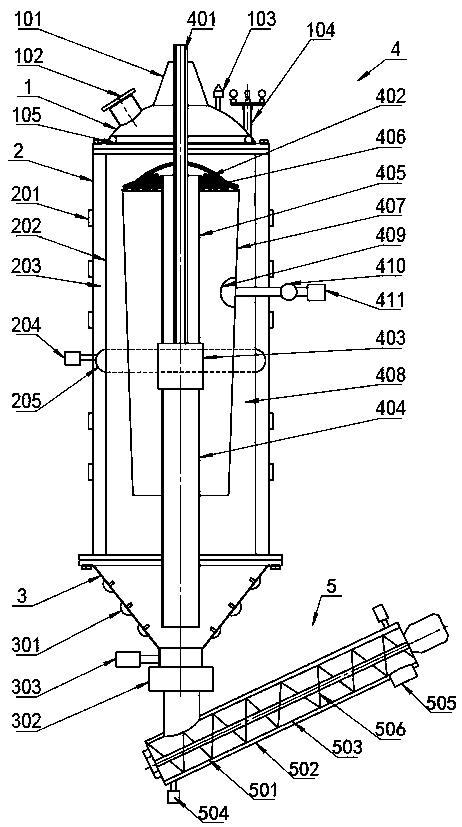
[0023] Chestnut buds are crushed to 60 mesh, put into the tank together with deionized water according to the solid-liquid ratio of 1: 10 (by mass), start the slurry pump 403 to rotate forward, and the slurry mixed with solid and liquid in the tank is sucked into the lower port of the suction pipe 404 Then, the upper port of the lift pipe 405 diffuses into the bamboo hat-shaped sieve plate 406, during which the liquid solvent in the slurry is filtered out from the large number of mesh holes in the lift pipe and the sieve plate, and reversely flows into the isolation cylinder 407. Downward, while the solid material is driven down by the continuously rotating scraper 402 on the sieve plate into the channel 408 on the periphery of the isolation cylinder. When the suction nozzle at the bottom of the tank is sucked into the channel, it goes up again, and after being filtered and separated, t...

example 2

[0028] Example 2, chestnut bract tannins were extracted using steam and ultrasonic waves.

[0029] The first step of moisturizing and fabric is exactly the same as Example 1. In the second step, because the pharmaceutical industry does not allow the use of microwaves to heat medicinal materials, microwaves are not used, and steam is used as a heat source to heat and break the solid material. Specifically, the tank is adjusted. The pressure regulating valve 103 on the cover controls the air pressure in the tank below 0.04Mpa, opens the steam valve 204 and the ultrasonic generator, and the pressure steam in the steam ring pipe 205 enters the channel filled with solid through the uniformly distributed air holes on the ring pipe Inside, continuously fumigate the descending solid material to cause it to expand and break the wall due to heat, during which the steam squeezes out the gap between the solid material due to air pressure, continuously rises to the top of the tank, and is r...


PUM


Abstract

The invention relates to an efficient and energy-saving extraction tank. The extraction tank comprises a tank body, a microwave ultrasonic generator and a liquid injection overflow mechanism which arearranged on the wall of the tank, a solid and liquid material separating and converging circulation channel in the tank, and a filter type spiral conveyor below the tank. When the tank is operated, the slurry flat turn circulation flow in the tank is changed into solid and liquid material upper-converting and lower-separating ascending and descending flow, so that microwave ultrasonic wave can perform targeted radiation on a solid material but not on a liquid material, the special structure of the tank allows liquid injection overflow and repeated retraction, and operations of liquid discharging and deslagging can be accomplished at the same time during discharging. The tank is obvious in energy-saving and time-saving effect, low in operation cost and high in efficiency, and provides a novel equipment selection for enterprise production.

Description

technical field [0001] The invention belongs to the field of extracting plant functional components, and in particular relates to a high-efficiency and greatly energy-saving extraction method and device with multiple functional coupling effects. Background technique [0002] Plants are important renewable resources that human society depends on for survival, and are also basic raw materials for industrial production. The extraction and utilization of functional components contained in them is the basic production mode of food, pharmaceutical, health care, biochemical and other industries. At present, traditional extraction methods such as maceration, infiltration, and decoction are still widely used. Although some emerging new technology methods such as microwave method and ultrasonic method have shown broad application prospects and advantages in plant extraction, due to the influence of Restricted by the inherent characteristics of various technologies, most of the new met...

Claims


Application Information

Patent Timeline
IPC IPC(8): B01D11/02
CPCB01D11/0265
Inventor 李肥生
Owner 李肥生
Learn More