Swivel construction method for bridge in water-rich area

A construction method and swivel technology, applied to bridges, bridge parts, bridge materials, etc., can solve the problems of large working space, time-consuming and labor-consuming, and affecting swivel, so as to achieve small equipment occupation, simplify positioning procedures, and ensure swivel body effect

Pending Publication Date: 2021-05-14
THE NO 6 ENG CO LTD OF CHINA RAILWAY 20TH BUREAU GRP
View PDF7 Cites 0 Cited by
  • Summary
  • Abstract
  • Description
  • Claims
  • Application Information

AI Technical Summary

Problems solved by technology

However, most of the swivel spherical joint bearings used for swivel bridges are located in the foundation pit, and they often face the risk of rainwater (flood) backflow during construction. The waterproof performance of the swivel device is required to be higher. At the same time, due to grouting, During the concrete pouring process, the cement slurry enters the swivel spherical hinge bearing due to washing and other reasons, which affects the swivel and makes the post-processing very troublesome
In addition, when installing the traditional swivel ball joint support, first pour the lower platform to the bottom of the ball joint frame, then hoist the frame, pour concrete to fix the frame, and then install the ball joint bottom plate, PTFE slide, and grease, etc. The upper plate is hoisted, tested and locked. The adjustment of the horizontal elevation of the ball joint structure mainly depends on the bolts between the frame and the lower plate. However, the horizontal position is not easy to adjust, and the adjustment requires a large working space, which is time-consuming. construction, which makes the structure positioning period longer, and it is easier for external impurities to enter the swivel spherical joint bearing, and the construction efficiency is low

Method used


Image

  • Swivel construction method for bridge in water-rich area
  • Swivel construction method for bridge in water-rich area
  • Swivel construction method for bridge in water-rich area

Examples


Embodiment Construction

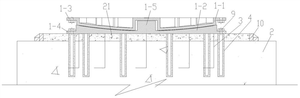
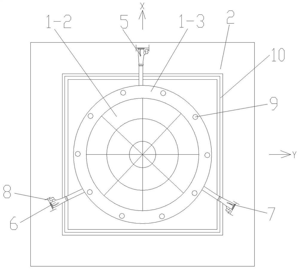
[0077] Such as Figure 1 to Figure 14 As shown, a swivel construction method of a bridge in a water-rich area of ​​the present invention, the method adopts a swivel spherical hinge support 62 arranged at the bottom of the main pier 22 of the bridge to realize the swivel, and the swivel spherical hinge support includes The upper ball pendulum 1-1, the lower ball pendulum 1-2, and the rotating shaft 1-5 arranged between the upper ball pendulum 1-1 and the lower ball pendulum 1-2, the upper ball pendulum 1-1 and the lower ball pendulum 1-2 2 vertical connection, the upper ball pendulum 1-1 is provided with an annular top seat 1-3, the lower ball pendulum 1-2 is provided with an annular base 1-4, and the annular base 1-4 is provided with a plurality of Circumferentially arranged anchor bolts 9, the method comprises the following steps:

[0078] Step 1. Installation of the temporary water-stop structure of the swivel spherical hinge support;

[0079] Step 2. The construction of t...


PUM


Abstract

The invention discloses a swivel construction method for a bridge in a water-rich area. The swivel construction method comprises the steps of firstly, installing a temporary water stop structure of a swivel spherical hinge support; 2, constructing a spherical hinge mounting bearing platform; 3, hoisting the swivel spherical hinge support; 4, adjusting the horizontal position of the swivel spherical hinge support; 5, fixing the swivel spherical hinge support; 6, constructing a rotator the bridge body structure; and 7, locking the swivel spherical hinge support and mounting the permanent water stop structure of the swivel spherical hinge support. The horizontal position of the swivel spherical hinge support is adjusted in three directions by arranging the jack, the occupied space is small, height positioning of the swivel spherical hinge support can be achieved only through one-time hoisting, the positioning and mounting speed of the swivel spherical hinge support is greatly increased, and meanwhile, water stop sealing structures are installed on the swivel spherical hinge support before and after swivel of the swivel beam, it is guaranteed that impurities can be prevented from entering the swivel spherical hinge support in the process that the swivel spherical hinge support waits for swivel, and therefore the swivel effect during swivel construction is guaranteed, and application and popularization are facilitated.

Description

technical field [0001] The invention belongs to the technical field of bridge construction, and in particular relates to a swivel construction method of bridges in water-rich areas. Background technique [0002] Bridge swivel construction is a new type of bridge construction technology developed in the 1940s. It can make full use of the favorable terrain near the pier (platform) for bridge superstructure construction, and can effectively solve special conditions such as crossing deep valleys, rivers, and existing lines. It has the advantages of not interfering with traffic, reducing construction difficulty and risk, etc. However, most of the swivel spherical joint bearings used for swivel bridges are located in the foundation pit, and they often face the risk of rainwater (flood) backflow during construction. The waterproof performance of the swivel device is required to be higher. At the same time, due to grouting, During the concrete pouring process, washing and other rea...

Claims


Application Information

Patent Timeline
Patent Type & Authority Applications(China)
IPC IPC(8): E01D21/08E01D19/00E01D19/04E01D19/08E01D101/24
CPCE01D21/08E01D19/00E01D19/046E01D19/083E01D2101/24
Inventor 段锋朱建锋吴旭亮刘德兵吴红兵马新文姜子麒古刚
Owner THE NO 6 ENG CO LTD OF CHINA RAILWAY 20TH BUREAU GRP
Why Eureka
Try Eureka