Gas turbine engine

A gas turbine and engine technology, applied in gas turbine devices, liquid fuel engines, engine components, etc., can solve the problems of overall fuel combustion reduction, short intake length, etc.

Pending Publication Date: 2021-05-14
ROLLS ROYCE PLC
View PDF1 Cites 0 Cited by
  • Summary
  • Abstract
  • Description
  • Claims
  • Application Information

AI Technical Summary

Problems solved by technology

Improved thrust at high angles of attack may allow for shorter intake lengths, resulting in reduced overall fuel burn

Method used


Image

  • Gas turbine engine
  • Gas turbine engine
  • Gas turbine engine

Examples


Embodiment Construction

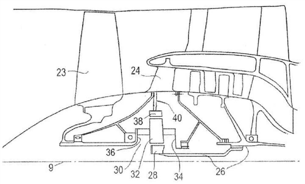
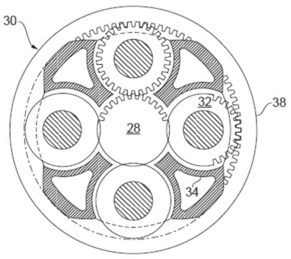
[0086] figure 1 A gas turbine engine 10 is shown having a main axis of rotation 9 . The engine 10 includes an air intake 12 and a propulsion fan 23 that generates two airflows: a core airflow A and a bypass airflow B. Gas turbine engine 10 includes a core 11 that receives a core flow A. As shown in FIG. The engine core 11 comprises a low pressure compressor 14 , a high pressure compressor 15 , a combustion device 16 , a high pressure turbine 17 , a low pressure turbine 19 and a core exhaust nozzle 20 in axial flow sequence. A nacelle 21 surrounds the gas turbine engine 10 and defines a bypass passage 22 and a bypass exhaust nozzle 18 . The bypass airflow B flows through the bypass passage 22 . The fan 23 is attached to and driven by the low pressure turbine 19 via a shaft 26 and a planetary gearbox 30 .

[0087] In use, the core gas stream A is accelerated and compressed by the low pressure compressor 14 and directed into the high pressure compressor 15 where further compr...


PUM

PropertyMeasurementUnit
Outer diameteraaaaaaaaaa

Abstract

The present disclosure relates to a gas turbine engine (10) for an aircraft, comprising: an engine core (11) comprising a turbine (19), a compressor (14) and a core shaft (26) connecting the turbine to the compressor; a fan (23) upstream of the engine core, the fan comprising a plurality of fan blades mounted for rotation about an engine axis, each blade of the plurality of fan blades having a leading edge and a trailing edge extending across a span of an airflow passage from a blade root to a blade tip; and a gearbox (30) receiving an input from the core shaft (26) and outputting a drive to the fan to drive the fan at a lower rotational speed than the core shaft, where the trailing edge of each blade is characterized by a metric M defined as a trailing edge angle by a rate of change of the trailing edge angle between 0.4 and 0.8 of the span divided by an area average, m is not less than about 4.

Description

technical field [0001] The present disclosure relates to gradients of trailing edge angles of fan blades in gas turbine engines. Background technique [0002] The ability of the fan in a turbofan gas turbine engine to supply thrust during high angle of attack flight regimes is an important factor, especially when considering engines with larger fan diameters such as eg 2 meters and above. Improved thrust at high angles of attack could allow for shorter intake lengths, resulting in reduced overall fuel burn. Contents of the invention [0003] According to a first aspect, there is provided a gas turbine engine for an aircraft comprising: [0004] an engine core comprising a turbine, a compressor and a core shaft connecting the turbine to the compressor; [0005] a fan located upstream of the engine core, the fan comprising a plurality of fan blades mounted for rotation about the engine axis, each blade of the plurality of fan blades having a leading edge and a trailing edg...

Claims


Application Information

Patent Timeline
IPC IPC(8): F02C3/113F02C7/04F02K3/06F04D29/38
CPCF02C3/113F02C7/04F02K3/06F04D29/384F05D2240/303F05D2240/304F05D2240/301F01D5/141F05D2220/36Y02T50/60F05D2220/323
Inventor B·莫汉库马尔M·J·威尔逊C·A·哈尔
Owner ROLLS ROYCE PLC
Why Eureka
Try Eureka