Parking brake cylinder and brake caliper unit
A parking brake and parking cylinder technology, applied in the field of rail transit, can solve the problems of poor safety and high use cost, and achieve the effects of reducing weight, low use cost and reducing volume
- Summary
- Abstract
- Description
- Claims
- Application Information
AI Technical Summary
Problems solved by technology
Method used
Image
Examples
Embodiment 1
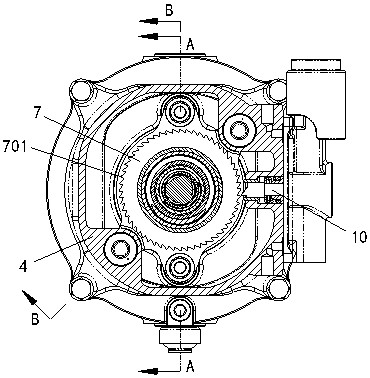
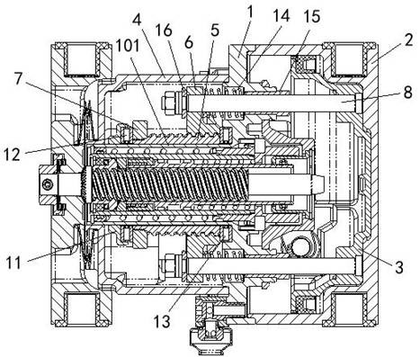
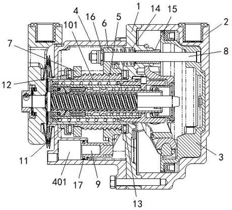
[0080] Example 1: see Figure 1 to Figure 3 , a parking brake cylinder comprising:
[0081] Intermediate 1;
[0082] The brake cylinder block 2 and the intermediate body 1 form a brake cylinder cavity;
[0083] The brake piston 3 is arranged in the brake cylinder cavity;
[0084] The parking cylinder 4 and the intermediate body 1 form a parking cylinder cavity, and two sealing cavities 401 are arranged in the parking cylinder 4, and the two sealing cavities are communicated with each other;
[0085] Force transmission unit, including:
[0086] The force transmission component is placed in the parking cylinder cavity, and the force transmission component includes a parking screw 5, a parking nut 6 sleeved on one end of the parking screw 5, and a ratchet 7 sleeved on the other end of the parking screw 5;
[0087] Two dowel rods 8 are arranged symmetrically around the circumference, one end of the dowel rod 8 is connected to the brake piston 3, and the other end is connected ...
Embodiment 2
[0113] Embodiment 2: Different from Embodiment 1, in this embodiment, see figure 1 , Figures 13 to 16 , the mitigation device 10 includes:
[0114] a pawl assembly, which cooperates with the ratchet tooth 701;
[0115] The mitigation body 1001 is provided with a mitigation cavity 1002, and one end of the mitigation body 1001 is provided with an air inlet 1003 that communicates with the mitigation cavity 1002;
[0116] The hand wedge 1004, one end of the first through hole 1005 on the circumference is arranged in the relief cavity 1002, and the other end extends out of the relief body 1001; the hand wedge 1004 in the relief cavity 1002 is provided with a pawl assembly on the hand wedge 1004 The matching wedge-shaped working surface 1006;
[0117] The first elastic member 1007 is arranged in the relief cavity 1002, between the hand relief wedge 1004 and the relief body 1001;
[0118] The sliding member 1008 is arranged in the first through hole 1005;
[0119] The limiting ...
Embodiment 3
[0137] Example 3: see Figure 21 , this embodiment provides a brake caliper unit, including a caliper arm assembly 18 and a parking brake cylinder 19, the parking brake cylinder 19 is hinged with the caliper arm assembly 18 through a connecting bolt 20, the parking brake cylinder 19. The parking brake cylinder described in Example 1 is used. Among them, the clamp arm acts as a force transmission lever, and the braking output force of the parking brake cylinder 19 is transmitted to the brake pad holder 21 through the clamp arm.
[0138] In this embodiment, the brake caliper unit is installed on the bogie frame of the rail transit vehicle, and the brake disc is tightened by the brake pad, and the kinetic energy of the train is transferred by the friction between the brake pad on the brake pad holder and the brake disc. Converted into heat dissipation to achieve the effect of slowing down or stopping.
PUM
 Abstract
Description
Claims
Application Information
 - R&D
- Intellectual Property
- Life Sciences
- Materials
- Tech Scout
- Unparalleled Data Quality
- Higher Quality Content
- 60% Fewer Hallucinations
Browse by: Latest US Patents, China's latest patents, Technical Efficacy Thesaurus, Application Domain, Technology Topic, Popular Technical Reports.
© 2025 PatSnap. All rights reserved.Legal|Privacy policy|Modern Slavery Act Transparency Statement|Sitemap|About US| Contact US: help@patsnap.com


