Wheeled vehicle emergency braking device

A technology of emergency braking and driving braking, which is applied in the direction of brakes, brake components, vehicle components, etc., can solve the problems of increasing the complexity of vehicle components, not being convenient to operate, and being unable to be started normally again, so as to improve the driving system Dynamic performance, simple structure, and low cost of use

Inactive Publication Date: 2013-12-18
CHINA NORTH VEHICLE RES INST
View PDF8 Cites 2 Cited by
  • Summary
  • Abstract
  • Description
  • Claims
  • Application Information

AI Technical Summary

Problems solved by technology

[0008] The above-mentioned devices often need to add some professional mechanical structures to the vehicle, increasing the complexity of the vehicle components, and the operation is not convenient enough
In addition, after the emergency braking device of some vehicles performs the braking operation, although the vehicle stops, it cannot be started normally. After the fault is repaired, the braking device must be released to return the vehicle to the use state. Great inconvenience to vehicle users

Method used


Image

  • Wheeled vehicle emergency braking device
  • Wheeled vehicle emergency braking device
  • Wheeled vehicle emergency braking device

Examples


Embodiment 1

[0036] Example 1: The emergency brake device is connected in parallel on the rear wheel brake pipeline

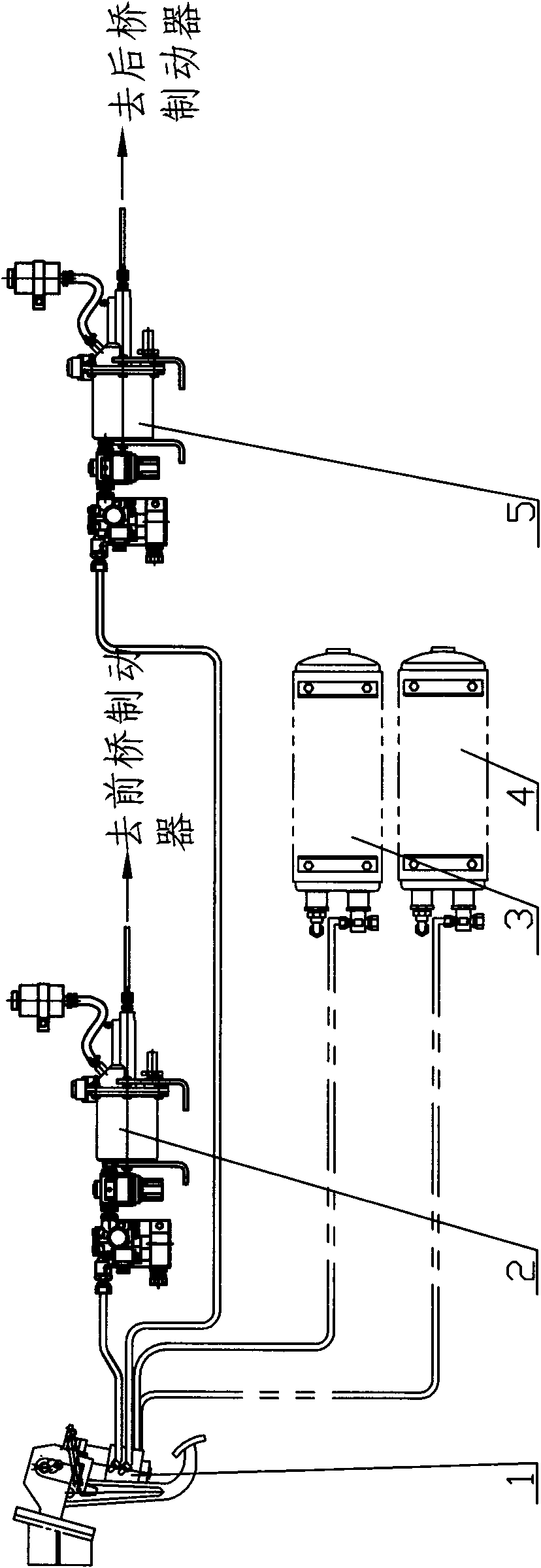
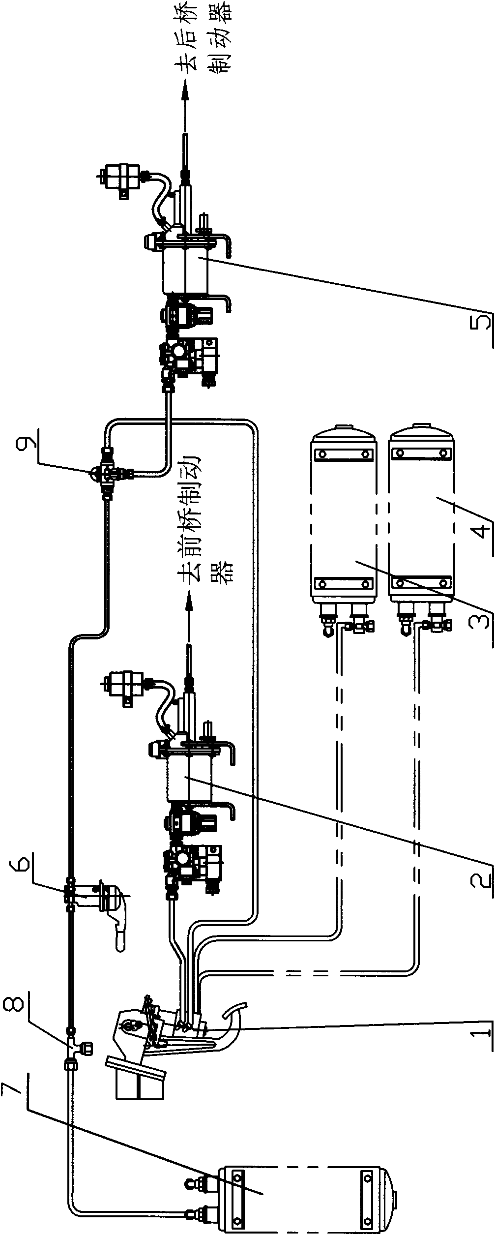
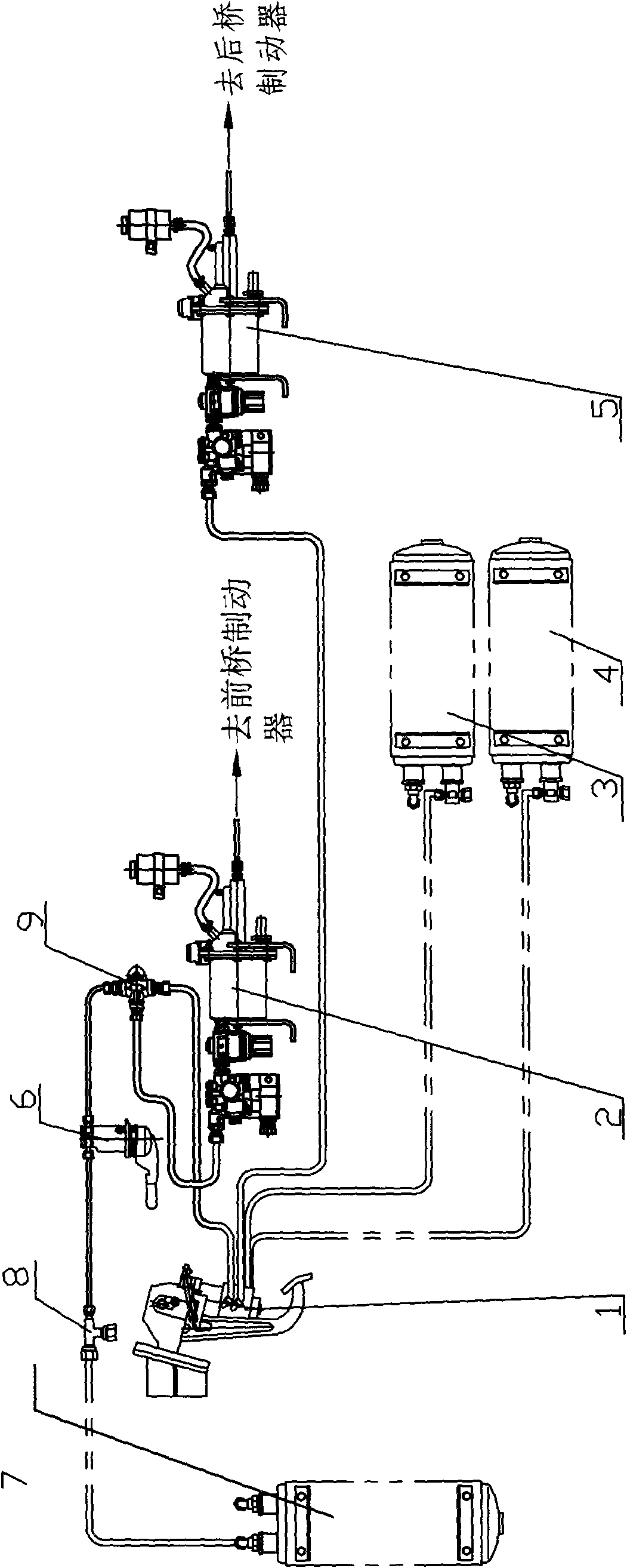
[0037] In the original car air top fluid brake system, such as figure 1 As shown in the diagram of the running brake pipeline of a traditional vehicle, the air volume of the front wheel gas storage cylinder 3, the rear wheel gas storage cylinder 4 and the parking spare gas cylinder 7 is supplied from the air compressor above the engine in the vehicle, and the driving brake is operated by manipulating the driving force. The brake valve 1 receives the gas from the front wheel gas storage cylinder 3 and the rear wheel gas storage cylinder 4 to act on the front wheel booster 2 and the rear wheel booster 5, so that the high pressure oil enters the front and rear wheel brakes for driving braking. move. Adding an emergency braking device is to add a three-way pipe joint 8, a hand brake valve 6 (the valve is progressive control) and a two-way check valve 9 on the pipeline of the o...

Embodiment 2

[0040] Example 2: The emergency brake device is connected in parallel on the front wheel brake pipeline

[0041] If the front wheel gas cylinder is empty, the pipeline is broken, or the service brake valve is damaged and stuck, the hand brake valve 6 can be operated to continue to control the front wheel booster 2 to brake the front wheel service brake.

Embodiment 3

[0042] Embodiment 3: The emergency braking device is connected in parallel on the front and rear wheel pipelines

[0043] The front wheel gas storage cylinder and the rear wheel gas storage cylinder are out of gas, the pipeline is broken, or the service brake valve is damaged and stuck, and the hand brake valve 6 can be operated to continue to control the front wheel booster 2 and the rear wheel booster 5 , apply the brakes to the front and rear service brakes.


PUM


Abstract

The invention provides a wheeled vehicle emergency braking device, which is suitable for wheeled vehicle of a full-pneumatic brake system or an air liquid brake system with a centre parking brake. The breaking device utilizes original apparatus of original vehicle brake system, increases a driving auxiliary braking system by increasing a few of spare parts and pipelines, and improves the driving brake security. The emergency brake can be combined with parking brake to solve the problem of insufficient parking brake force and improve the parking security. The emergency braking device can be connected with a front wheel brake pipeline or a rear wheel brake pipeline in parallel, or simultaneously, be connected with the front and rear wheel brake pipelines in parallel. The emergency braking device adds a three-way pipe joint, a manual brake valve and a two-way check valve on the pipeline of original parking spare air storage bottle so that the brake pipeline becomes a dual-pipeline. The device of the invention is featured with simple structure, low use cost, flexible arrangement and good generality, can effectively improve the parking security and driving brake security.

Description

technical field [0001] The invention belongs to the field of an emergency brake device for a wheeled vehicle with a full-air brake system or an air-top liquid brake system with a central parking brake, and in particular relates to an emergency brake device for a wheeled vehicle. Background technique [0002] Automobile brake system is divided into service brake system, parking brake system, emergency brake system and auxiliary brake system. The brake system used to reduce the speed of a moving car to a stop is called a service brake system; the brake system used to keep a parked car in place is called a parking brake system; In the event of a braking system failure, the braking system that ensures that the car can still slow down or stop is called an emergency braking system; in conventional wheeled vehicles, a service braking system and a parking braking system are must-haves for the vehicle. [0003] At present, the brake types of many wheeled vehicles in China are mostly...

Claims


Application Information

Patent Timeline
Patent Type & Authority Patents(China)
IPC IPC(8): B60T15/06
Inventor 段希杰杜志岐唐镜朱勤仪聂春贵范婧
Owner CHINA NORTH VEHICLE RES INST
Why Eureka
Try Eureka