Electric proportional pressure valve

A proportional pressure valve, electrical technology, applied in the field of proportional pressure valve, can solve the problems of slow response, short service life, complex structure, etc.

Pending Publication Date: 2021-05-14
环路科技(常州)有限公司
View PDF0 Cites 1 Cited by
  • Summary
  • Abstract
  • Description
  • Claims
  • Application Information

AI Technical Summary

Problems solved by technology

[0007] The technical problem to be solved by the present invention is: in order to solve the problems of complex structure, short service life, low control precision and slow response speed caused by two sets of high-frequency electromagnetic valves for pressure regulation in the electric proportional pressure valve in the prior art, now Provides an electric proportional pressure valve

Method used


Image

  • Electric proportional pressure valve
  • Electric proportional pressure valve
  • Electric proportional pressure valve

Examples


Embodiment 1

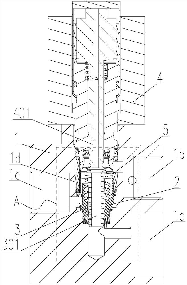
[0058] Such as Figure 1-4 Shown, an electric proportional pressure valve, including:

[0059] The valve body 1 has a valve chamber 1d, a P1 port 1a, a P2 port 1b, and a P3 port 1c;

[0060] The valve seat 2 has a valve hole 201, and the valve seat 2 is fixed at the bottom end of the valve cavity 1d;

[0061] The valve core 3 has a central hole 301 through it, and the bottom end of the valve core 3 is inserted in the valve hole 201 and is slidably connected with the valve hole 201;

[0062] The proportional electromagnet 4 is set on the top of the valve cavity 1d and fixed on the valve body 1;

[0063] The fixed cover 5 is fixed in the valve chamber 1d, and is sleeved on the outside of the valve seat 2. The top of the fixed cover 5 has a top edge 501, and the fixed cover 5, the valve seat 2 and the valve core 3 are formed between the fixed cover 5 and the valve core 3. The first cavity 6 communicated with P1 port 1a, the position between the proportional electromagnet 4 and...

Embodiment 2

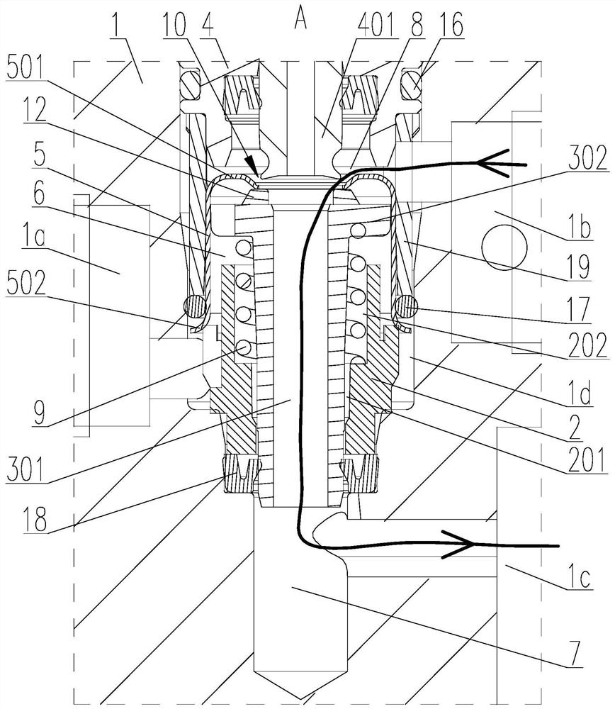
[0070] The sealing unit includes a gasket 12, the gasket 12 is fixed on the top end surface of the valve core 3, and the top opening of the central hole 301 is located in the gasket 12;

[0071] Such as figure 2 As shown, in the first working state, the top edge 501 of the fixed cover 5 is against the gasket 12, that is, the valve core 3 is firmly pressed against the top edge of the fixed cover 5 by the gasket 12 under the action of the elastic element 9 501 to ensure that the first cavity 6 and the second cavity 7 are kept isolated from each other; the push rod 401 is separated from the gasket 12 to ensure that the first gap 10 formed between the push rod 401 of the proportional electromagnet 4 and the valve core 3 can Make the upper opening of the central hole 301 communicate with the second chamber 7;

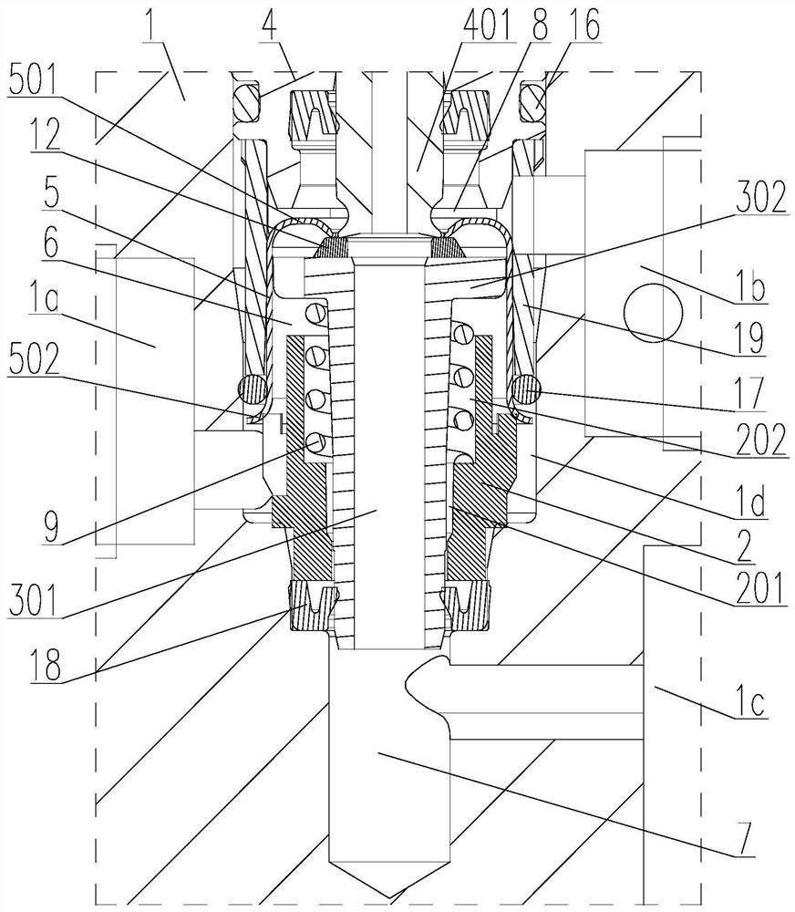
[0072] Such as image 3 As shown, during the second working state, the top edge 501 of the fixed cover 5 is against the sealing gasket 12, that is, the valve core 3 makes...


PUM


Abstract

The invention relates to the technical field of proportional pressure valves, in particular to an electric proportional pressure valve. The electric proportional pressure valve comprises a valve body, a valve seat, a valve element, a proportional electromagnet, a fixed cover and an elastic element, wherein the electric proportional pressure valve has a first working state, a second working state and a third working state. The design that the fixed cover is matched with the valve element is ingeniously utilized, so that the single proportional electromagnet can enable the electric proportional pressure valve to be freely switched among the three working states. The electric proportional pressure valve has the advantages that the structure is simple and reliable, the failure rate is low, the cost is low, the service life can be prolonged, and the harsh application environment of a vehicle can be adapted; and the proportional electromagnet directly drives the valve element to act, so that the control precision is high and the response is fast; and the closed-loop control over pressure can be achieved by means of air pressure logic, so that the power consumption of the proportional electromagnet can be effectively reduced, meanwhile the development difficulty of a control system is reduced, program control is simple and easy to implement, and the market prospect is good.

Description

technical field [0001] The invention relates to the technical field of proportional pressure valves, in particular to an electric proportional pressure valve. Background technique [0002] Electric proportional pressure valve, as a highly integrated mechatronic product, is the core of electric proportional control technology and represents the development direction of fluid control technology. It is widely used in factory automation and vehicle control. The existing electric proportional pressure valve is usually controlled by two sets of two-position two-way high-frequency solenoid valves, which have the following problems: [0003] First, the two sets of high-frequency solenoid valves need non-stop action to adjust the pressure. If one of them fails, the valve will fail and the service life will be shortened; [0004] Second, there is a pilot air chamber, due to the compressibility of the gas, its control accuracy is low and the response speed is slow; [0005] Third, po...

Claims


Application Information

Patent Timeline
Patent Type & Authority Applications(China)
IPC IPC(8): F16K11/044F16K27/02F16K31/06
CPCF16K11/044F16K27/0263F16K27/029F16K31/0627F16K31/0675
Inventor 李春风郑皆琴
Owner 环路科技(常州)有限公司
Why Eureka
Try Eureka