Optical detecting device

A technology of optical detection and detection strips, which is applied in the direction of using optical devices, measuring devices, instruments, etc., and can solve the problem of not being able to correctly identify boundary changes

Active Publication Date: 2021-05-14
PIXART IMAGING INC
View PDF20 Cites 0 Cited by
  • Summary
  • Abstract
  • Description
  • Claims
  • Application Information

AI Technical Summary

Problems solved by technology

However, the traditional lift detection algorithm cannot correctly identify boundary changes when the lift height of the optical mouse is less than one millimeter. Therefore, how to design an optical detection device that can detect the slight lift of the optical mouse is the key development of related industries. one of the goals

Method used


Image

  • Optical detecting device
  • Optical detecting device
  • Optical detecting device

Examples


Embodiment Construction

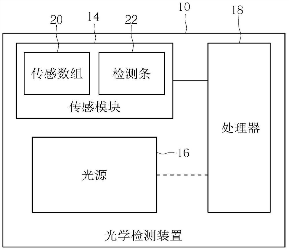
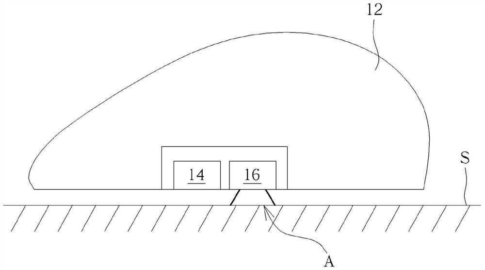
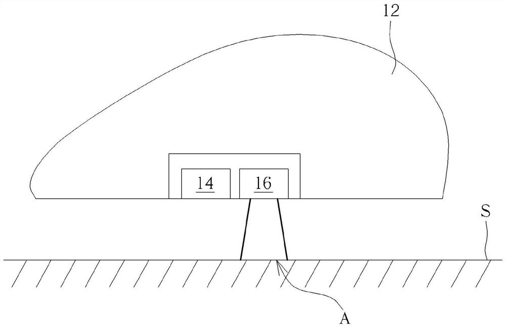
[0036] see Figure 1 to Figure 3 , figure 1 is a functional block diagram of the optical detection device 10 of the embodiment of the present invention, figure 2 and image 3 It is a schematic diagram of lifting the optical navigation device 12 to different heights according to the embodiment of the present invention. The optical navigation device 12 can have an optical detection device 10 . The optical navigation device 12 can be raised or translated relative to the work surface S. As shown in FIG. The optical detection device 10 can be used to detect vertical movement and horizontal movement of the optical navigation device 12 relative to the work surface S. As shown in FIG. The optical detection device 10 may include a sensing module 14 , a light source 16 and a processor 18 . The processor 18 can be electrically connected to the sensing module 14 and can also be selectively electrically connected to the light source 16 .

[0037] The light source 16 can project ligh...


PUM


Abstract

An optical detecting device capable of detecting a lift height of an optical navigation apparatus is disclosed. The optical detecting device includes a sensor module and a processor. The sensor module includes a sensor array and at least one detector strip. The sensor array is adapted to acquire navigation information of the optical navigation apparatus moved relative to a working surface by sensing an illumination area, and the detector strip has a detection region across an edge of the illumination area. The processor is electrically connected to the sensor module, and adapted to compute the lift height of the optical navigation apparatus relative to the working surface according to a detection result of the detector strip. According to the optical detecting device, the small-amplitude lifting height of the optical navigation equipment can be accurately detected in real time by using the detection strip.

Description

technical field [0001] The invention relates to an optical detection device, in particular to an optical detection device capable of detecting a small lift of an optical navigation device. Background technique [0002] Traditional optical mice utilize a single-zone pixel array to detect bright areas projected onto the work surface. The image obtained by the pixel array is used to analyze and judge the navigation information and the lifting information. When the optical mouse moves on the work surface, the movement of any point in the image can be converted into navigation information; when the optical mouse is lifted relative to the work surface, the boundary of the bright area begins to move, and the image quality of the bright area decreases, so the boundary and image Changes in mass are converted to lift information. However, the traditional lift detection algorithm cannot correctly identify boundary changes when the lift height of the optical mouse is less than one mil...

Claims


Application Information

Patent Timeline
Patent Type & Authority Applications(China)
IPC IPC(8): G01B11/06G06F3/0354
CPCG01B11/0608G06F3/03541G06F3/0317G01B11/002G06F3/0304
Inventor 彭桂莉林炜绩李秀晶
Owner PIXART IMAGING INC
Why Eureka
Try Eureka