Blade micropore angle measuring method

A technology of angle measurement and small microholes, applied in the field of measurement, can solve the problems of long processing time, large error, inaccurate measurement angle, etc., and achieve the effect of improving the qualified rate

Pending Publication Date: 2021-05-14
CHINA HANGFA SOUTH IND CO LTD
View PDF2 Cites 0 Cited by
  • Summary
  • Abstract
  • Description
  • Claims
  • Application Information

AI Technical Summary

Problems solved by technology

[0010] 1. It can only judge whether the angle (that is, the processing parameters) adjusted by the fixture and / or machine tool is correct. For example, the angle is measured by processing a large hole of φ1 with a measuring rod. After the angle is qualified, the angle of a small hole with a diameter of φ0.25 is processed by default. Qualified, but the actual large hole of φ1 is not directly related to the diameter of φ0.25 (the parameter settings of the EDM equipment are different), this measurement method has a large error, usually between 1° and 1.5°
[0011] 2. The inner cavity of the aero-engine blade 100 has complex circuits and ribs. After the measuring rod enters the inner cavity, it is easy to interfere, causing the measuring rod to tilt to one side, and the measurement angle is inaccurate
[0012] 3. The aeroengine blades 100 are all made of high-temperature alloy materials, so the processing is difficult and the processing time is long. Usually, it takes about 15 minutes to process a φ1 hole
[0013] 4. The aero-engine blade 100 after processing the φ1 hole can only be scrapped, and 2 to 3 blades need to be scrapped for each batch of blade processing, and the price of each blade is 10,000 to 30,000, which causes great waste

Method used


Image

  • Blade micropore angle measuring method
  • Blade micropore angle measuring method
  • Blade micropore angle measuring method

Examples


Embodiment Construction

[0037] In order to have a clearer understanding of the technical features, purposes and effects of the present invention, the specific implementation manners of the present invention will now be described with reference to the accompanying drawings. Wherein, the same parts adopt the same reference numerals.

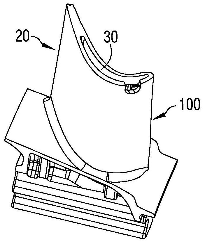
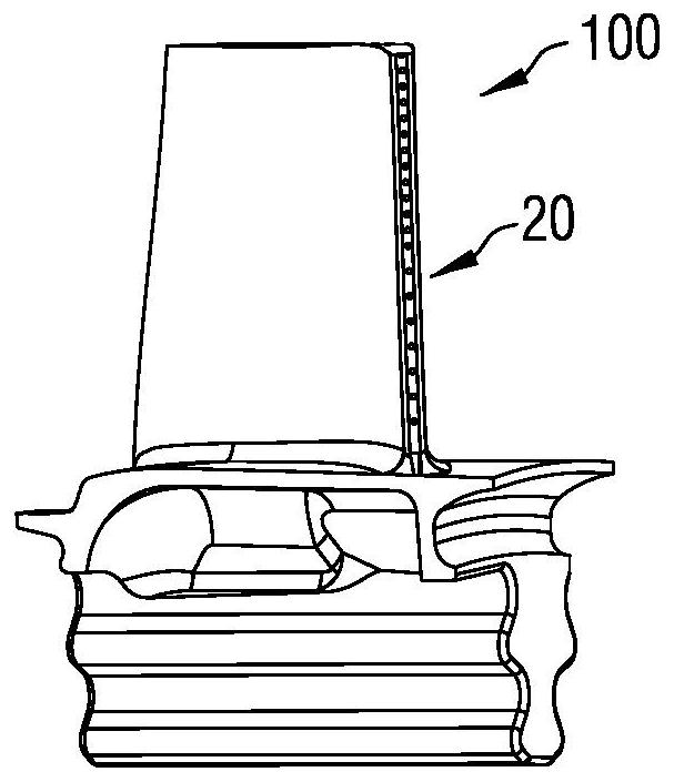
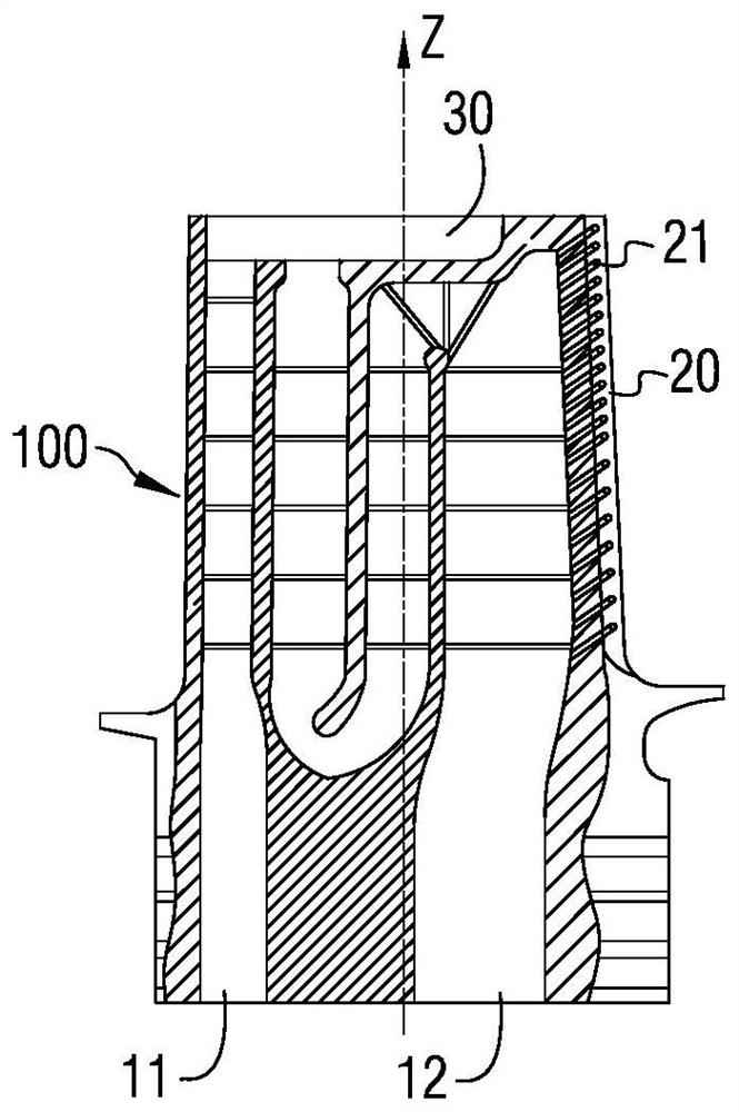
[0038] As described in the background technology, in view of the problem that the angle of the air film hole 21 cannot be directly measured because the existing hole diameter is generally between φ0.25mm~φ0.5mm, and the depth is not less than 6mm, the inventors carried out the principle After an in-depth analysis, the root cause is summarized as follows:

[0039] 1. Since the diameter of the air film hole 21 is too small, there is no existing standard measuring stick that can be inserted into it for measurement of hole angle extension.

[0040] 2. Since the diameter of the air film hole 21 is too small, and the inner cavity of the aeroengine blade 100 has complex circuit...


PUM


Abstract

A blade micropore angle measuring method comprises the following steps: step A, preparing a measuring needle according to the diameter of a film hole, step B, enabling the end of an insertion part of the measuring needle prepared in the step A to be in contact with a port of the film hole, forming negative pressure in an inner cavity of an aero-engine blade, so that the insertion part is sucked into the air film hole until the extension part is in contact with the port of the air film hole, and the installation of the measuring needle is completed; step C, using an optical measurement mode to complete angle measurement of the gas film hole, and after measurement data is obtained, taking out the measurement needle along the axis direction of the measurement needle so as to complete angle measurement of the gas film hole. According to the method, the angle of the air film hole of the blade can be directly measured, real air film hole angle data can be obtained, and physical damage to the blade cannot be caused in the measuring process.

Description

technical field [0001] The invention relates to the field of measurement technology, in particular to a method for measuring the real angle of a small microhole on an aeroengine blade. Background technique [0002] For modern aero-engines, with the increasing performance, the working environment of various components, especially the blades, is getting worse and worse. Therefore, various technical means need to be used to deal with it. For example, for turbine blades, in order to ensure their To maintain good mechanical properties under high temperature and high pressure environment, it is necessary to cast the blade into a hollow structure, set the exhaust passage in the inner cavity, and process multiple The air film hole is connected to the inner cavity, so that the cold air entering the inner cavity can be ejected from the air film hole of the blade body, and while taking away a certain amount of heat from the blade body, a layer of cold air protection layer is formed on ...

Claims


Application Information

Patent Timeline
Patent Type & Authority Applications(China)
IPC IPC(8): G01B11/26G01B11/00
CPCG01B11/005G01B11/26
Inventor 黄文俊邹沙王豪肖俊袁艳
Owner CHINA HANGFA SOUTH IND CO LTD
Why Eureka
Try Eureka