Human eye safety laser ranging machine and method

A laser rangefinder, eye-safe technology, applied in the measurement distance, measurement device, line-of-sight measurement and other directions, can solve the problems of indistinguishable pulse shape, low repetition frequency, blindness of personnel, etc., to achieve good economic use value, Improve the accuracy of distance measurement and improve the effect of measuring distance

Active Publication Date: 2021-05-14
苏州同人激光科技有限公司
View PDF8 Cites 1 Cited by
  • Summary
  • Abstract
  • Description
  • Claims
  • Application Information

AI Technical Summary

Problems solved by technology

At present, the wavelengths used by lasers for distance measurement are 1.06 μm, 1.5 μm, and 10.6 μm, etc., but because the 1.06 μm and 10.6 μm wavelengths allow the human eye to have less exposure, it is easy to be sensitive to the human eye in an instant. Cause great harm, then easily bring the danger of blinding to personnel in battlefield and training; within) and low output energy (microjoule level), and because the conventional method of counting photon pulses is used, when the measurement distance increases, the returned energy decreases sharply, and the pulse shape is difficult to distinguish, so it limits its further application

Method used


Image

  • Human eye safety laser ranging machine and method
  • Human eye safety laser ranging machine and method
  • Human eye safety laser ranging machine and method

Examples


Embodiment Construction

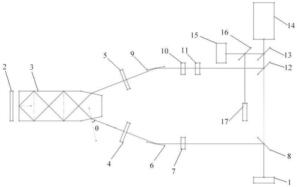
[0054] In order to make the object, technical solution and advantages of the present invention clearer, the present invention will be further described in detail below in conjunction with the accompanying drawings and embodiments. It should be understood that the specific embodiments described here are only used to explain the present invention, not to limit the present invention.

[0055] It should be noted that when a component is referred to as being “fixed on” or “disposed on” another component, it may be directly or indirectly located on the other component. When an element is referred to as being "connected to" another element, it can be directly or indirectly connected to the other element. The terms "upper", "lower", "left", "right", "front", "rear", "vertical", "horizontal", "top", "bottom", "inner", "outer", etc. The indicated orientation or position is based on the orientation or position shown in the drawings, and is only for convenience of description, and should...


PUM

PropertyMeasurementUnit
wavelengthaaaaaaaaaa
refractive indexaaaaaaaaaa

Abstract

The invention provides a human eye safety laser ranging machine and method. The human eye safety laser ranging machine is simple to operate, small in size, high in test precision and capable of outputting band laser safe to human eyes. The human eye safety laser ranging machine comprises a laser and a detector; the laser comprises a light source, erbium glass and a first reflector and a second reflector; the first reflector and the second reflector are arranged at the light emitting end of the erbium glass; the included angle between the normal of the first reflector and the second reflector and the normal of the light emitting surface of the erbium glass is a Brewster angle; the first reflector, the second reflector and the erbium glass form a V-shaped resonant cavity; light emitted by the light source enters the erbium glass and then is emitted from the first reflector and the second reflector; and the light emitted from the first reflector sequentially passes through a first total reflection mirror, an acous to-optic frequency shifter, a first beam splitter and the detector; the light emitted from the second reflector sequentially passes through a second total reflection mirror, a Q-switched crystal, a Faraday optical rotation isolator, a second beam splitter, a third beam splitter and a telescopic system and then is emitted to a to-be-detected target; and light scattered or reflected by the to-be-detected target sequentially passes through the third beam splitter, the second beam splitter and the first beam splitter and then enters the detector.

Description

technical field [0001] The invention relates to the technical field of laser equipment, in particular to an eye-safe laser distance measuring machine and method. Background technique [0002] Laser ranging is the earliest application of laser in the military, and it is also one of the most mature technologies. Laser ranging uses the transmission time of light between two objects to calculate the distance length. The laser in the laser ranging machine has a good divergence , the divergence angle is relatively small, and the target position can be measured more accurately. [0003] At present, laser range finders are widely used in military weapons. The use of laser range finders has greatly improved the probability of tanks, drones and long-range artillery weapons hitting targets. Contemporary warfare is characterized by small scale and high speed, which requires military weapons to be able to conduct precise guidance, quick response and maneuverability in action, and laser ...

Claims


Application Information

Patent Timeline
Patent Type & Authority Applications(China)
IPC IPC(8): G01S17/48
CPCG01S17/48Y02A90/10
Inventor 赵辉
Owner 苏州同人激光科技有限公司
Why Eureka
Try Eureka