Direct type light-emitting device

A light-emitting device, direct-type technology, applied in optics, nonlinear optics, instruments, etc., can solve the problems of uneven brightness and limited effect of direct-type backlight modules

Active Publication Date: 2021-05-14
SHENZHEN LONGLI TECH CO LTD
View PDF10 Cites 0 Cited by
  • Summary
  • Abstract
  • Description
  • Claims
  • Application Information

AI Technical Summary

Problems solved by technology

[0006] However, the larger the distribution area of ​​the above-mentioned LED array in the prior art, the more the number of light sources in the formed LED array, the smaller the spacing, and the more uniform the light output.

Method used


Image

  • Direct type light-emitting device
  • Direct type light-emitting device
  • Direct type light-emitting device

Examples


Embodiment 1

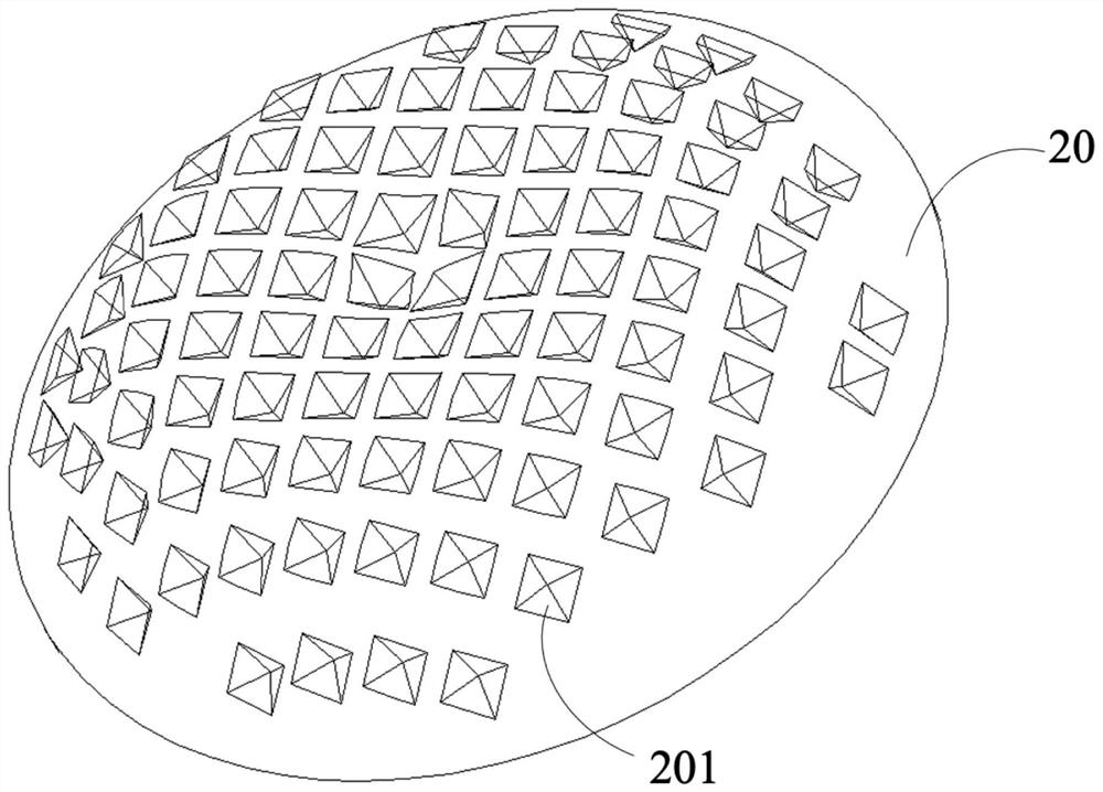
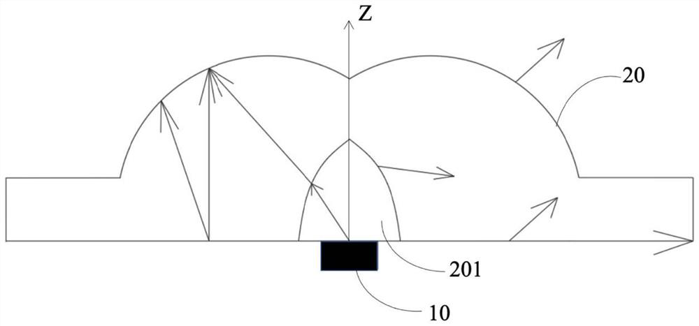
[0033] First, through Figure 2-6 , the direct-type light-emitting device according to Embodiment 1 of the present invention will be described. The direct-type light-emitting device of Embodiment 1 of the present invention, such as image 3 As shown, a direct lighting device includes a plurality of LED light sources 10 and a plurality of optical lenses 20 coupled to the LED light sources 10 and positioned above the LED light sources 10 . The optical lens 20 is provided with a hollow structure 201 which is radially symmetrical to the light source and the optical axis of the optical lens 20 . Such as figure 2 As shown, the outer surface of the optical lens 20 is provided with a micro-diffusion structure 202 . In the hollow structure 201, the angle between the tangent plane of the surface near the optical axis and the optical axis is smaller than the angle between the tangent plane of the surface far from the optical axis and the optical axis; The density of the micro-diffus...

Embodiment 2

[0040] Please refer to Figure 7 , is a schematic structural view of the optical lens of the direct light-emitting device according to Embodiment 2 of the present invention. Only the differences between Embodiment 2 and Embodiment 1 will be described below, and the similarities will not be repeated here.

[0041] The hollow structure 201 forms a near-cone mechanism 202 along the optical axis, and the top angle of the near-cone mechanism 202 is farther away from the LED light source 10 . The reflectance of the light emitted by the LED light source 10 at the apex angle of the near-cone mechanism 202 is higher, so that the direct-type light-emitting device can achieve a wider light transfer function and a larger diffusion angle. A plurality of optical lenses 20 are integrally connected.

Embodiment 3

[0043] Please refer to Figure 8 , is a schematic structural view of the optical lens of the direct light-emitting device according to Embodiment 3 of the present invention. In the following, only the differences between Embodiment 3 and Embodiment 1 will be described, and the similarities will not be repeated here.

[0044] The optical lens 20 forms a near-cone structure 202 along the optical axis, and the top angle of the near-cone structure 202 is close to the LED light source 10 . The reflectance of the light emitted by the LED light source 10 at the apex angle of the near-cone mechanism 202 is higher, so that the direct-type light-emitting device can achieve a wider light transfer function and a larger diffusion angle.


PUM


Abstract

The invention discloses a direct type light-emitting device. The direct type light-emitting device includes a plurality of LED light sources and a plurality of optical lenses coupled to and over the LED light sources. Each optical lens is provided with a hollow structure which is radially symmetrical to the optical axes of the light source and the optical lens. A micro diffusion structure is arranged on the outer surface of each optical lens. In the hollow structure, the included angle between the tangent plane of the surface near the optical axis and the optical axis is smaller than that between the tangent plane of the surface far away from the optical axis and the optical axis; the density of the micro diffusion structures near the optical axis is larger than that of the micro diffusion structures far away from the optical axis, so that light incident to the surface near the optical axis is reflected and redirected at a higher proportion, and a light field with uniform light intensity distribution is formed above the direct type light emitting device.

Description

technical field [0001] The invention relates to semiconductor device manufacturing and an optical system, in particular to a direct-type light-emitting device. Background technique [0002] The liquid crystal panel itself included in the liquid crystal display device does not emit light. Therefore, in the liquid crystal display device, a backlight device serving as a surface light source device is provided on the back side of the liquid crystal panel as a light source for illuminating the liquid crystal panel. The main components of the direct-type backlight device include optical modules, diffuser plates, LED light sources, and reflectors. In this structure, how to effectively reduce the LED light source and diffuser plate without increasing the cost and the uniformity of light output? It is an important subject to meet the requirement of reducing the thickness of the backlight device due to the distance between them. [0003] US Patent Publication No. 20080231780 disclos...

Claims


Application Information

Patent Timeline
IPC IPC(8): G02F1/13357
CPCG02F1/133606G02F1/133611G02F1/133605G02F1/133603
Inventor 张小齐刘政彭益庄世强黄小芸
Owner SHENZHEN LONGLI TECH CO LTD
Why Eureka
Try Eureka