A geometric calibration method and device for multi-focal plane splicing large field of view off-axis camera

A technology of geometric calibration and multi-focal planes, which is applied in image analysis, instrumentation, calculation, etc.

Active Publication Date: 2022-03-01
CHANGGUANG SATELLITE TECH CO LTD
View PDF8 Cites 0 Cited by
  • Summary
  • Abstract
  • Description
  • Claims
  • Application Information

AI Technical Summary

Problems solved by technology

[0004] The present invention provides a geometric calibration method and device for multi-focal plane splicing and large field of view off-axis cameras to solve the problem of high-precision ground geometry calibration of multi-focal plane splicing and large field of view off-axis cameras

Method used


Image

  • A geometric calibration method and device for multi-focal plane splicing large field of view off-axis camera
  • A geometric calibration method and device for multi-focal plane splicing large field of view off-axis camera
  • A geometric calibration method and device for multi-focal plane splicing large field of view off-axis camera

Examples


specific Embodiment approach 2

[0047] Specific embodiment two, combine 3 to Figure 5 Describe this embodiment. This embodiment is a method for calibrating using the geometric calibration device of a multi-focal plane splicing large-field-of-view off-axis camera described in Embodiment 1. The steps of the calibration method are as follows:

[0048] First, the stitching area of ​​the multi-focal plane is calibrated;

[0049] (1) According to the optical parameters of the off-axis camera to be tested, select a collimator and slit target with a suitable focal length and aperture: the aperture of the collimator is greater than or equal to the aperture of the camera, and the focal length of the collimator is f Collimator is the camera focal length f Camera The width of the slit target imaging on the focal plane of the camera should be about 3 times the pixel width, that is, the relationship between the slit width w and the pixel size a is:

[0050]

[0051] (2) adjust the optical axis of the light pipe in the...

specific Embodiment approach 3

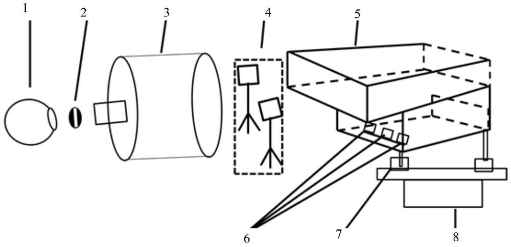
[0070] Specific embodiment three, combine Figure 1 to Figure 5 Describe this implementation mode, this implementation mode is the embodiment of specific implementation mode 1:

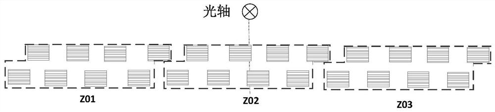
[0071] 1) The focal length of the off-axis three-mirror remote sensing camera with a large field of view is set to 4850mm, the field of view is 16°, the pixel size of the detector is 10 microns, and the pixel column is 6144. There are 5 spectral bands in total, in order to cover the entire imaging surface , using 24 detectors;

[0072] 2) According to the optical parameters of the designed camera, select a collimator, a slit target, a high-precision single-axis turntable, and a Leica theodolite to build a ground geometric calibration device, such as figure 1 As shown, its main parameters are: the focal length of the collimator is 30m, the aperture is 800mm, the slit width corresponding to the full spectrum segment is 0.2mm, the slit width corresponding to the multi-spectral spectrum segment is 0.8mm,...


PUM


Abstract

A geometric calibration method and device for multi-focal plane splicing and large field of view off-axis cameras, which relate to the field of optical precision measurement technology, and solve the high-precision ground geometry of space remote sensing long focal length, large field of view, and multi-focal plane splicing off-axis cameras Calibration problem. First, use the collimator, slit target, and the splicing area of ​​each detector on the focal plane of theodolite to test, and calculate the relative positional relationship between the detectors, and then use the high-precision single-axis turntable to place the slit targets at different intervals on the camera. The uplink and downlink detectors perform imaging, process the collected images, extract the coordinates of the center of mass and convert them to the same coordinate system through the relative positional relationship, and calculate the principal point, principal distance and distortion calibration results of the camera through calculation formulas. The present invention completes high-precision geometric calibration for cameras in any focal plane splicing form by selecting a suitable collimator, slit target, and single-axis turntable.

Description

technical field [0001] The invention relates to the technical field of optical precision measurement, in particular to a multi-focal plane mosaic method for ground geometry calibration of a large field of view off-axis remote sensing camera. Background technique [0002] With the development of remote sensing imaging technology, the geometric accuracy of on-orbit imaging is getting higher and higher. The laboratory geometric calibration of cameras has become an important task. High-precision ground calibration can effectively reduce the camera’s on-orbit test cycle and improve Geometric positioning accuracy enhances the efficiency of satellite applications. In recent years, some universities and research institutions at home and abroad have carried out in-depth research on ground geometric calibration methods for remote sensing cameras, including precision angle measurement methods, self-calibration methods and their applied target image extraction algorithms, distortion mod...

Claims


Application Information

Patent Timeline
Patent Type & Authority Patents(China)
IPC IPC(8): G06T7/80
CPCG06T7/80
Inventor 李艳杰刘江马驰丛杉珊李兴光
Owner CHANGGUANG SATELLITE TECH CO LTD
Why Eureka
Try Eureka