
Geometric calibration method and device for multi-focal-plane spliced large-view-field off-axis camera

A geometric calibration, multi-focal plane technology, used in image data processing, instrumentation, computing, etc.

Active Publication Date: 2021-05-14
CHANGGUANG SATELLITE TECH CO LTD
View PDF8 Cites 2 Cited by
  • Summary
  • Abstract
  • Description
  • Claims
  • Application Information

AI Technical Summary

Problems solved by technology

[0004] The present invention provides a geometric calibration method and device for multi-focal plane splicing and large field of view off-axis cameras to solve the problem of high-precision ground geometry calibration of multi-focal plane splicing and large field of view off-axis cameras

Method used


Image

  • Geometric calibration method and device for multi-focal-plane spliced large-view-field off-axis camera
  • Geometric calibration method and device for multi-focal-plane spliced large-view-field off-axis camera
  • Geometric calibration method and device for multi-focal-plane spliced large-view-field off-axis camera

Examples


specific Embodiment approach 2

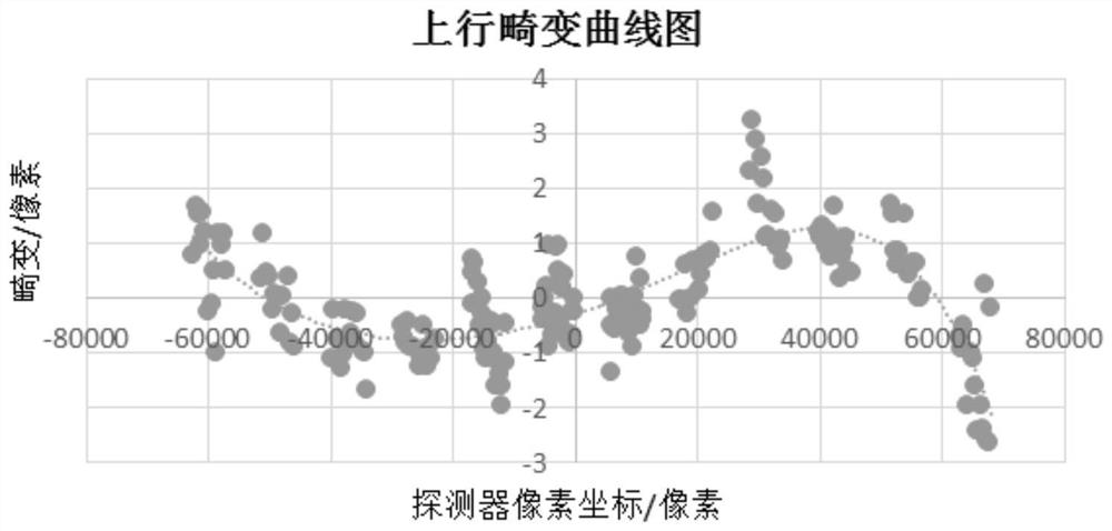
[0047] Specific embodiment two, combine 3 to Figure 5 This embodiment is described. This embodiment is a method for calibrating using the geometric calibration device of a multi-focal plane splicing large field of view off-axis camera described in Embodiment 1. The steps of the calibration method are as follows:

[0048] First, the stitching area of ​​the multi-focal plane is calibrated;

[0049] (1) According to the optical parameters of the off-axis camera to be tested, select a collimator and slit target with a suitable focal length and aperture: the aperture of the collimator is greater than or equal to the aperture of the camera, and the focal length of the collimator is f Collimator is the camera focal length f Camera The width of the slit target imaging on the focal plane of the camera should be about 3 times the pixel width, that is, the relationship between the slit width w and the pixel size a is:

[0050]

[0051] (2) adjust the optical axis of the light pipe in...

specific Embodiment approach 3

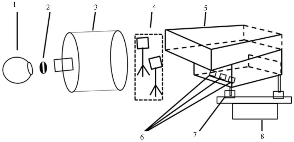
[0070] Specific embodiment three, combine Figure 1 to Figure 5 Describe this implementation mode, this implementation mode is the embodiment of specific implementation mode 1:

[0071] 1) The focal length of the off-axis three-mirror remote sensing camera with a large field of view is set to 4850mm, the field of view is 16°, the pixel size of the detector is 10 microns, and the pixel column is 6144. There are 5 spectral bands in total, in order to cover the entire imaging surface , using 24 detectors;

[0072] 2) According to the optical parameters of the designed camera, select a collimator, a slit target, a high-precision single-axis turntable and a Leica theodolite to build a ground geometric calibration device, such as figure 1 As shown, its main parameters are: the focal length of the collimator is 30m, the aperture is 800mm, the slit width corresponding to the full spectrum segment is 0.2mm, the slit width corresponding to the multi-spectral spectrum segment is 0.8mm, ...


PUM


Abstract

The invention discloses a geometric calibration method and device for a multi-focal-plane spliced large-view-field off-axis camera, relates to the technical field of optical precision measurement, and solves the problem of high-precision ground geometric calibration of a space remote sensing long-focal-length, large-view-field and multi-focal-plane spliced off-axis camera. Firstly, a collimator, slit targets and a theodolite are used for testing splicing areas of all detectors on a focal plane, the relative position relation between the detectors is obtained through calculation, then through a high-precision single-axis rotary table, the slit targets are imaged on all the detectors on the uplink and the downlink of a camera at unequal intervals, collected images are processed, and the detection result is obtained. And extracting a centroid coordinate, converting the centroid coordinate to the same coordinate system through a relative position relation, and calculating through a resolving formula to obtain a principal point, a principal distance and a distortion calibration result of the camera. According to the invention, by selecting a proper collimator, a slit target and a single-axis turntable, high-precision geometric calibration of a camera in any focal plane splicing form is completed.

Description

technical field [0001] The invention relates to the technical field of optical precision measurement, in particular to a multi-focal plane mosaic method for ground geometry calibration of a large field of view off-axis remote sensing camera. Background technique [0002] With the development of remote sensing imaging technology, the geometric accuracy of on-orbit imaging is getting higher and higher. The laboratory geometric calibration of cameras has become an important task. High-precision ground calibration can effectively reduce the camera’s on-orbit test cycle and improve Geometric positioning accuracy enhances the efficiency of satellite applications. In recent years, some universities and research institutions at home and abroad have carried out in-depth research on ground geometric calibration methods for remote sensing cameras, including precision angle measurement methods, self-calibration methods and their applied target image extraction algorithms, distortion mod...

Claims


Application Information

Patent Timeline
Patent Type & Authority Applications(China)
IPC IPC(8): G06T7/80
CPCG06T7/80
Inventor 李艳杰刘江马驰丛杉珊李兴光
Owner CHANGGUANG SATELLITE TECH CO LTD
Learn More