Wall surface machining device for building decoration engineering

A technology of architectural decoration engineering and processing equipment, which is applied in the direction of stone processing tools, stone processing equipment, work accessories, etc., and can solve problems such as dust, worker injury, air pollution, etc.

Active Publication Date: 2021-05-18
建邦技术集团有限公司
View PDF9 Cites 0 Cited by
  • Summary
  • Abstract
  • Description
  • Claims
  • Application Information

AI Technical Summary

Problems solved by technology

[0005] In order to overcome the manual punching, not only does it require more physical strength, but also the punching will drop more dust, which will increase the trouble of cleaning in the later stage and easily lead to The air is polluted by dust, which in turn causes some harm to the staff. The purpose of the present invention is to provide a wall processing device for architectural decoration projects that can automatically collect dust and prevent dust from polluting the air.

Method used


Image

  • Wall surface machining device for building decoration engineering
  • Wall surface machining device for building decoration engineering
  • Wall surface machining device for building decoration engineering

Examples


Embodiment 1

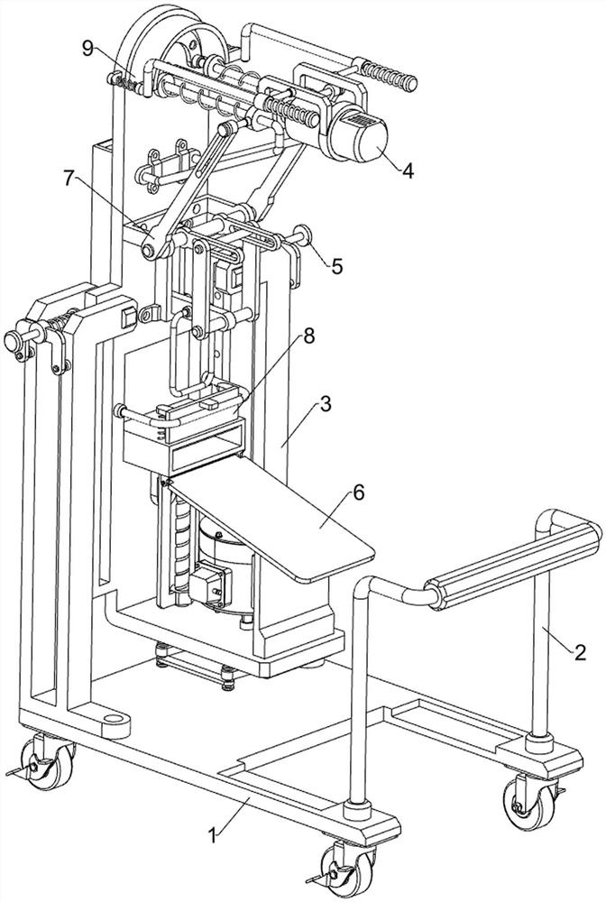
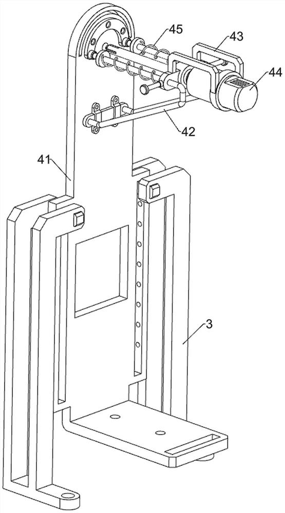
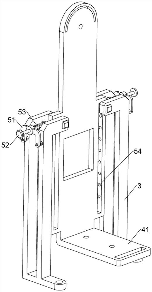
[0028] A wall processing device for building decoration engineering, such as Figure 1-3 As shown, it includes a mobile seat 1, a handle 2, a guide frame 3, a processing assembly 4 and a limit assembly 5. The upper right side of the mobile seat 1 is connected with a handle 2, and the left side of the mobile seat 1 passes through the front and rear sides. A guide frame 3 is fixedly connected to the bolt, and a processing assembly 4 is arranged between the guide frames 3 , and a limit assembly 5 is arranged on the guide frame 3 , and the limit assembly 5 cooperates with the processing assembly 4 .

[0029] When it is necessary to process the wall surface, control the handle 2 to move the moving seat 1, and then move the device to the edge of the wall, and then control the limit component 5 to adjust the position of the processing component 4, and no longer control the limit after the adjustment is completed Component 5, the limit component 5 automatically resets to fix the proce...

Embodiment 2

[0035] On the basis of Example 1, such as figure 1 , Figure 4 , Figure 5 , Image 6 with Figure 7 As shown, a collection assembly 6 is also included, and the collection assembly 6 includes a collection frame 61, an inclined plate 62, a vertical plate 63, a reduction motor 64, a screw mandrel 65, a connecting block 66, a swing block 67 and a connecting plate 68, and the mounting plate 41 The upper sliding type is provided with a collection frame 61, the bottom right side of the collection frame 61 is rotatably connected with a slant plate 62, the right side of the mounting plate 41 is provided with a vertical plate 63, the vertical plate 63 is in contact with the slanting plate 62, and the mounting plate 41 The bottom is provided with a reduction motor 64, the bottom of the mounting plate 41 is rotatably connected with a screw 65, the underside of the collection frame 61 is connected with a connection block 66, the connection block 66 is connected with the screw 65 by thr...


PUM


Abstract

The invention relates to a wall surface machining device, in particular to a wall surface machining device for building decoration engineering. According to the purpose, the wall surface machining device for building decoration engineering is provided and can automatically collect dust and prevent the dust from polluting air. The wall surface machining device for building decoration engineering comprises a moving seat, a grip mounted on the movable seat, guide frames mounted on two sides of the movable seat, a machining assembly mounted between the guide frames and limiting assemblies mounted on the guide frame and matched with the machining assembly. The wall surface machining device is provided with a collecting assembly, so that during wall surface machining, generated dust can fall into a collecting frame and then can slide down and be collected through an inclined plate, and then the situation that dust falls during machining, and the later cleaning trouble is increased is prevented.

Description

technical field [0001] The invention relates to a wall surface processing device, in particular to a wall surface processing device for building decoration engineering. Background technique [0002] In order to protect the main structure of the building, improve the use function of the building and beautify the building, various treatment processes are carried out on the inner and outer surfaces and spaces of the building by using decorative materials or accessories. [0003] When processing the wall, it is often necessary to punch the wall. Generally, the wall is punched manually. When the hole is manually punched, the staff needs to hold an electric drill, and then the wall needs to be punched. Drilling holes in places, manual drilling not only requires more physical strength, but also will drop more dust, which will increase the trouble of cleaning in the later stage, and easily cause the air to be polluted by dust, which will cause some damage to the staff . [0004] T...

Claims


Application Information

Patent Timeline
Patent Type & Authority Applications(China)
IPC IPC(8): B28D1/14B28D7/00B28D7/02
CPCB28D1/146B28D7/00B28D7/02
Inventor 李明
Owner 建邦技术集团有限公司
Why Eureka
Try Eureka