
Steel plate composite beam operating platform

A technology for operating platforms and composite beams, applied in bridges, bridge construction, erection/assembly of bridges, etc., can solve problems such as difficulties in installing and dismantling cast-in-place bridge deck brackets and formwork, and worker safety cannot be guaranteed

Pending Publication Date: 2021-05-18
ROAD & BRIDGE SOUTH CHINA EINGINEERING CO LTD +1
View PDF0 Cites 0 Cited by
  • Summary
  • Abstract
  • Description
  • Claims
  • Application Information

AI Technical Summary

Problems solved by technology

[0003] In order to overcome the above technical problems, especially the difficulty in the installation and disassembly of steel plate composite girders, the installation and disassembly of cast-in-place bridge deck brackets and formwork, and the problem that the safety of workers cannot be guaranteed during the installation and disassembly process, the following technical solutions are proposed:

Method used


Image

  • Steel plate composite beam operating platform
  • Steel plate composite beam operating platform
  • Steel plate composite beam operating platform

Examples


Embodiment 1

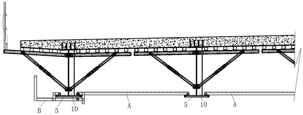
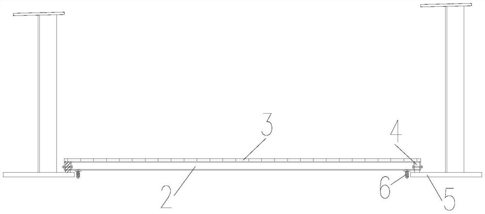
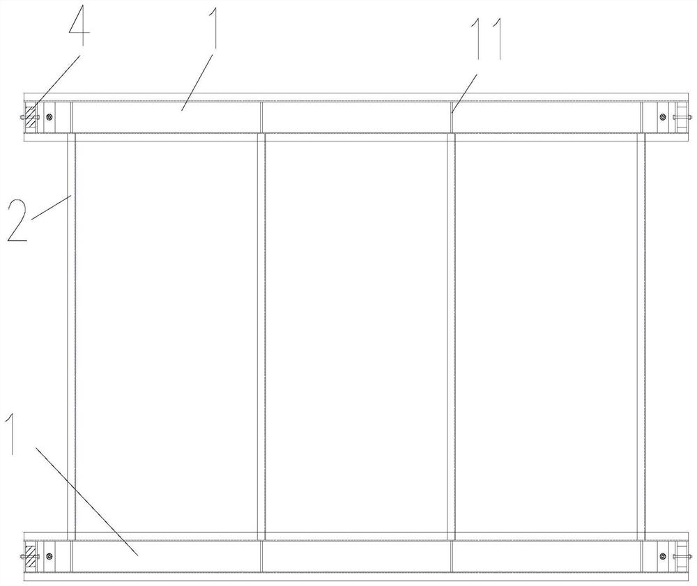
[0035] The steel plate composite beam operating platform A in the first embodiment provided by the application, such as Figure 1 to Figure 3 As shown, when the two ends of the main beam 1 are set higher than the walking platform, the rollers 4 are arranged on the top surface of the walking platform, that is, the two ends of the main beam 1 are arranged above the steel main beam bottom plate 5, and the rollers 4 at the two ends of the main beam 1 are set On the steel girder floor 5 top surfaces of two adjacent steel girders, that is, the rollers 4 at both ends of the main girder 1 travel on the top surfaces of the steel girder bottom plates 5 . Because the longitudinal girders of the same steel girder run through the longitudinal direction of the bridge, after the steel plate composite girder operating platform is installed on the steel girder bottom plate 5, one installation can be realized, and all parallel connections, The installation and disassembly of cast-in-place bridg...

Embodiment 2

[0038] The steel plate composite beam operating platform B in the second embodiment provided by the application, such as figure 1 , Figure 4 and Figure 5As shown, when the main beam 1 is set lower than the walking platform, the main beam 1 is arranged under the steel main beam bottom plate 5, and two roller connectors 7 connected with the rollers 4 are arranged at both ends of the main beam 1, and the two roller connectors 7 are connected The rollers 4 are arranged on two opposite and adjacent walking platforms, that is, arranged on the top surface of the steel main beam floor 5 on both sides of the same longitudinal beam along the bridge, and the roller connectors 7 are arranged on the two ends of the main beam 1 Above, and one end away from the main beam extends to the longitudinal beam 10 in the steel main beam, and the roller 4 is arranged at the end of the extension section of the roller connector 7 to the steel main beam longitudinal beam 10, so as to ensure that the ...


PUM


Abstract

The invention relates to a steel plate composite beam operating platform which comprises main beams parallel to each other and an operating platform structure arranged between the main beams, wherein rolling wheels running in the first direction are arranged at the two ends of each main beam, and the rolling wheels of the same main beam are clamped on adjacent walking platforms respectively. A limiting piece right opposite to the side face of the walking platform is arranged at the end of the main beam. The operating platform provided by the embodiment of the invention is simple in structure and convenient to install, full-bridge slippage can be rapidly achieved, the construction period of parallel connection installation and cast-in-place bridge deck bracket and formwork installation and disassembly is shortened, and the construction progress is accelerated.

Description

technical field [0001] The invention relates to the technical field of building construction, in particular to a steel plate composite beam operating platform. Background technique [0002] At present, the steel plate composite girder bridge has a simple structure, wide application conditions for design and construction, convenient fabrication and construction, and has been widely used. It is a very economical and durable structure. Horizontal connections are set between the two ends of the longitudinal beams, truss-type cross-links are set between the spans, and the main beams on both sides and the main beams at both ends are set with lower parallel supports. However, in the prior art, the large-area hollowed-out parts between the main girders of the steel plate composite girders and between the beams make it difficult to install and disassemble the steel plate composite girders in parallel, and to install and disassemble the cast-in-place bridge deck brackets and formwork....

Claims


Application Information

Patent Timeline
Patent Type & Authority Applications(China)
IPC IPC(8): E01D21/00
CPCE01D21/00
Inventor 赵富立吴正华郭晓伟黎磊李建谢南峰
Owner ROAD & BRIDGE SOUTH CHINA EINGINEERING CO LTD
Learn More