Multifunctional LED eye protection table lamp
A multifunctional, table lamp technology, applied in the mechanical field, can solve problems such as inconvenient use, inconvenient work, and isolation of electronic equipment
- Summary
- Abstract
- Description
- Claims
- Application Information
AI Technical Summary
Problems solved by technology
Method used
Image
Examples
Embodiment 1
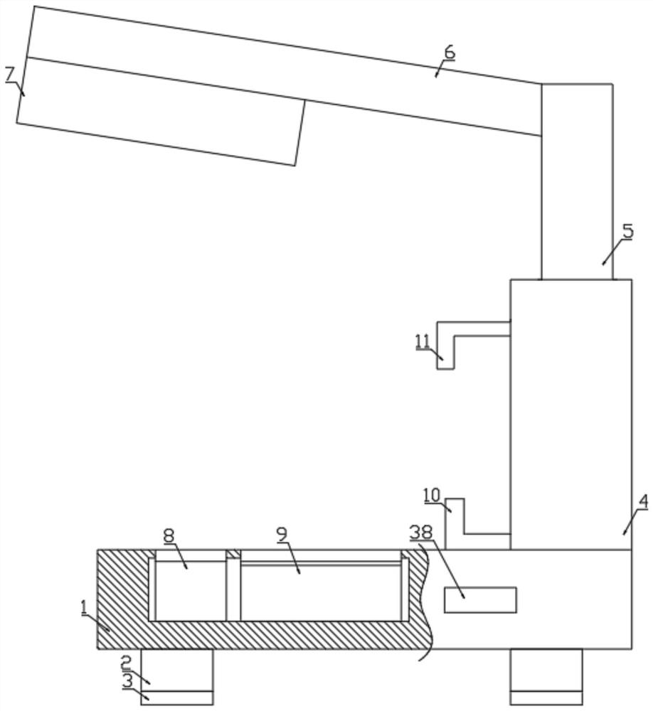
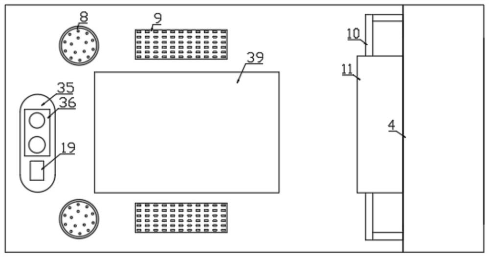
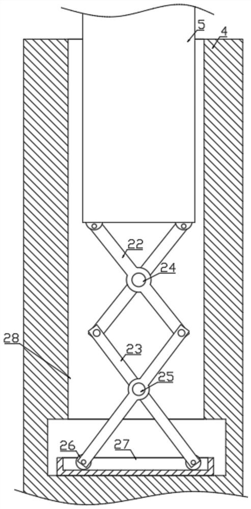
[0028] Example 1: Please refer to Figure 1-8 , in an embodiment of the present invention, a multifunctional LED eye-protecting table lamp includes a support base 1, a storage rod 4 is fixedly arranged on the right side of the upper end of the support base 1, and an adjustment rod 5 is slidably installed on the upper side of the storage rod 4, and the inside of the storage rod 4 A device chamber 28 is provided, and the bottom side of the device chamber 28 is fixed with a limit plate 27. The lower end of the adjustment rod 5 is connected to the oil push rod a22 on the front and rear sides, and the lower end of the push rod a22 is connected to the push rod b23. The lower end of the push rod b23 is equipped with a roller 26 And the rollers 26 are fitted inside the limit plate 27, the push rods a22 are connected with each other and the left side of the connection point is fixed with the rotation shaft a24, the push rods b23 are connected with each other and the left side of the con...
Embodiment 2
[0030] Embodiment 2: This invention also provides another embodiment, which is improved on the basis of the above embodiment. The lower side of the support seat 1 is fixed with a gravity column 2 and the lower side of the gravity column 2 is installed Anti-skid plate 3 is arranged to enhance the stability at the bottom of the device.
[0031] The working principle of the present invention: the signal is transmitted to the motor through the control button a19, and the motor drives the rotating wheel b33 and the transmission wheel b31 to rotate through the rotating shaft b25 and the rotating shaft c37. The transmission rope b34 on the rotating wheel a32 makes the rotating shaft a24 drive the pushing rod a22 to move upwards, and the pushing rod a22 drives the pushing rod b23 connected to it to move upwards and drives the roller 26 connected to its lower end to roll inside the limit plate 27, thereby making the The adjustment rod 5 drives the lamp tube 15 to move up through the su...
PUM
 Abstract
Description
Claims
Application Information
 - R&D
- Intellectual Property
- Life Sciences
- Materials
- Tech Scout
- Unparalleled Data Quality
- Higher Quality Content
- 60% Fewer Hallucinations
Browse by: Latest US Patents, China's latest patents, Technical Efficacy Thesaurus, Application Domain, Technology Topic, Popular Technical Reports.
© 2025 PatSnap. All rights reserved.Legal|Privacy policy|Modern Slavery Act Transparency Statement|Sitemap|About US| Contact US: help@patsnap.com


