Testing device for testing misfire of building ground material and product thereof
A technology for ground materials and test devices, which can be used in measuring devices, using mechanical devices, analyzing materials, etc., and can solve problems such as low data reliability.
- Summary
- Abstract
- Description
- Claims
- Application Information
AI Technical Summary
Problems solved by technology
Method used
Image
Examples
Embodiment 1
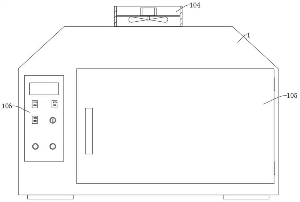
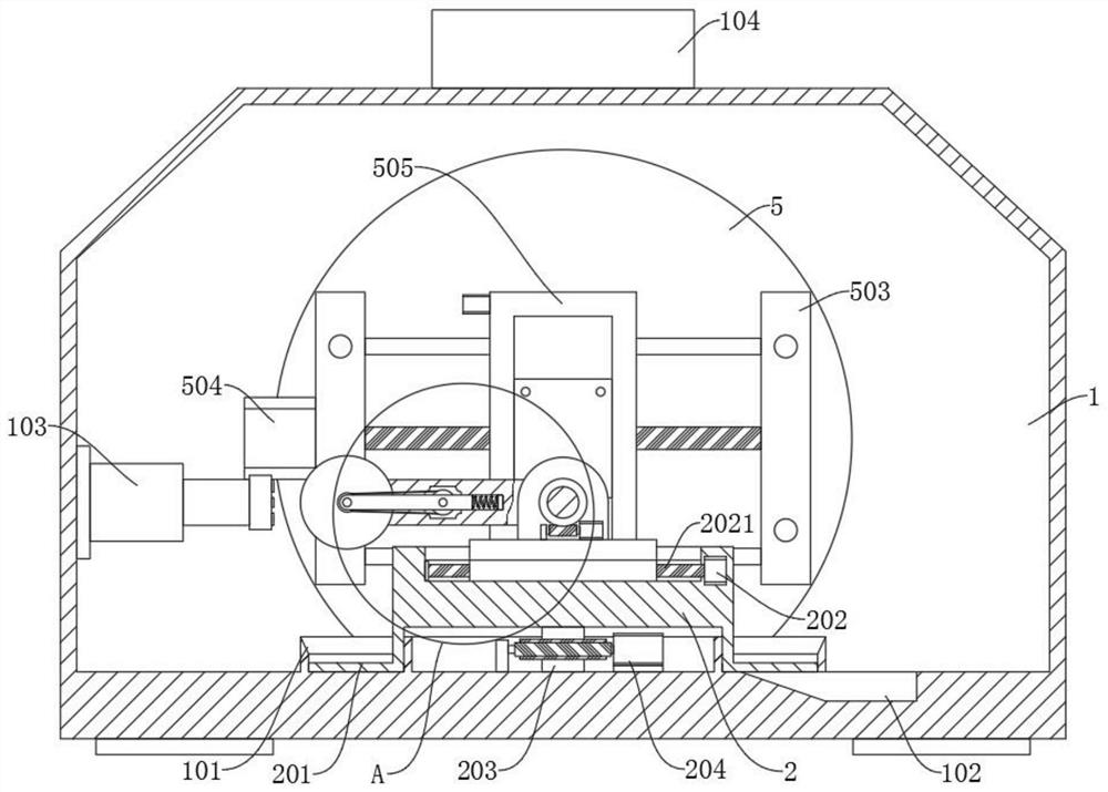
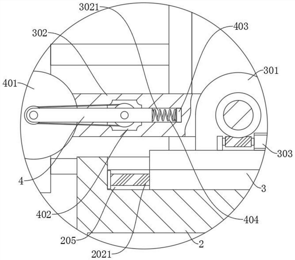
[0032] refer to Figure 1-3, a test device for testing the non-flammability of building floor materials and products thereof, comprising a detection box 1 and a grinding wheel 401, the detection box 1 is connected with a steering table 2 for rotation, and the detection box 1 is provided with a rotating table for driving the steering table 2 The top of the steering table 2 is provided with a chute 205, the chute 205 is slidably connected to the corner table 3, the chute 205 is provided with a second drive unit for driving the corner table 3 to slide, and the corner table 3 rotates Connected with a test rod 302, the corner table 3 is provided with a third driving part for driving the test rod 302 to rotate, a limit groove 3021 is provided in the test rod 302, and a sensor frame 4 is slidably connected in the limit groove 3021, and the grinding wheel 401 rotates Connected to one end of the sensing frame 4, the sensing frame 4 is provided with a fourth driving part for driving the...
Embodiment 2
[0035] refer to Figure 2-3 and Figure 7 , the first driving part includes a first motor 204, the first motor 204 is fixedly connected to the bottom inner wall of the detection box 1, the output end of the first motor 204 is fixedly connected to a first worm, and the bottom of the turntable 2 is fixedly connected to a positioning shaft 203 , the positioning shaft 203 is fixedly connected with the first worm gear meshed with the first worm, the inside of the detection box 1 is fixedly connected with the collection ring 101, the inside of the detection box 1 is provided with a collection groove 102 communicating with the collection ring 101, and the steering table The bottom of 2 is fixedly connected with a conveying ring 201, and the conveying ring 201 is rotatably connected in the collecting ring 101, and a plurality of groups of inclined sweeping rods 2011 are arranged at intervals in the conveying ring 201, and the second driving part includes a second motor 202, and the se...
Embodiment 3
[0038] refer to image 3 , the fourth driving part includes a fourth motor 402, the fourth motor 402 is fixedly connected on the sensor frame 4, the output end of the fourth motor 402 is fixedly connected with the first pulley, and the rotating shaft of the grinding wheel 401 is fixedly connected with the second belt The first pulley is connected to the second pulley by belt rotation. The sampling assembly includes a pressure sensor 403. The pressure sensor 403 is fixedly connected to the limit groove 3021. The end of the sensor frame 4 away from the grinding wheel 401 is fixedly connected with a buffer spring 404. The buffer spring 404 is against the pressure sensor 403 .
[0039] During the test, the fourth motor 402 drives the grinding wheel 401 to rotate at a high speed through a belt drive. When pressure is applied to the grinding wheel 401, the sensor frame 4 will slide in the limit groove 3021, thereby transmitting the pressure to the pressure sensor 403 for sampling. ...
PUM
 Abstract
Description
Claims
Application Information
 - R&D
- Intellectual Property
- Life Sciences
- Materials
- Tech Scout
- Unparalleled Data Quality
- Higher Quality Content
- 60% Fewer Hallucinations
Browse by: Latest US Patents, China's latest patents, Technical Efficacy Thesaurus, Application Domain, Technology Topic, Popular Technical Reports.
© 2025 PatSnap. All rights reserved.Legal|Privacy policy|Modern Slavery Act Transparency Statement|Sitemap|About US| Contact US: help@patsnap.com


