
Permanent magnet linear synchronous motor feeding device

A permanent magnet linear synchronization and feeding device technology, applied in the direction of electromechanical devices, manufacturing motor generators, electrical components, etc., can solve problems such as motor damage, easily scratched coils, and difficult installation of rotors

Inactive Publication Date: 2021-05-18
环一军
View PDF0 Cites 0 Cited by
  • Summary
  • Abstract
  • Description
  • Claims
  • Application Information

AI Technical Summary

Problems solved by technology

[0003] When installing the rotor of permanent magnet linear synchronous motor, because the surface of the rotor is relatively rough, it is easy to scratch the coil and cause damage to the motor. It is necessary to effectively separate the rotor from the stator with the coil to avoid damage to the coil. The rotor of the magnetic linear synchronous motor is difficult to install, and now there is an urgent need for a permanent magnet linear synchronous motor feed device to solve the above problems

Method used


Image

  • Permanent magnet linear synchronous motor feeding device
  • Permanent magnet linear synchronous motor feeding device
  • Permanent magnet linear synchronous motor feeding device

Examples


Embodiment Construction

[0020] In order to make the technical means, creative features, goals and effects achieved by the present invention easy to understand, the present invention will be further described below in conjunction with specific embodiments.

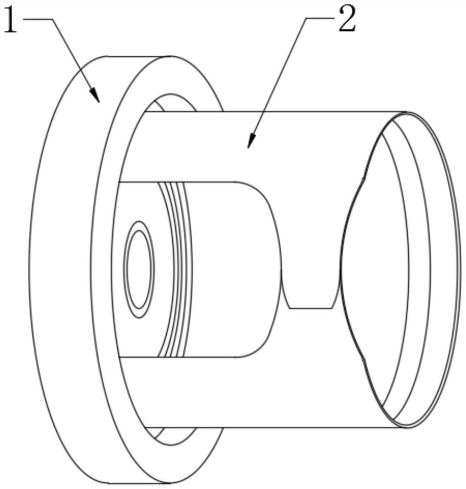
[0021] see Figure 1-Figure 5 , The present invention provides a technical solution: a permanent magnet linear synchronous motor feeding device, including a feeder main body 1 and a rotor feeding mechanism 2 , and the rotor feeding mechanism 2 is arranged inside the feeder main body 1 .

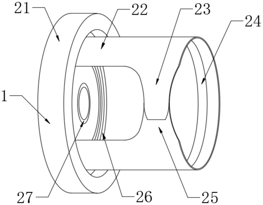
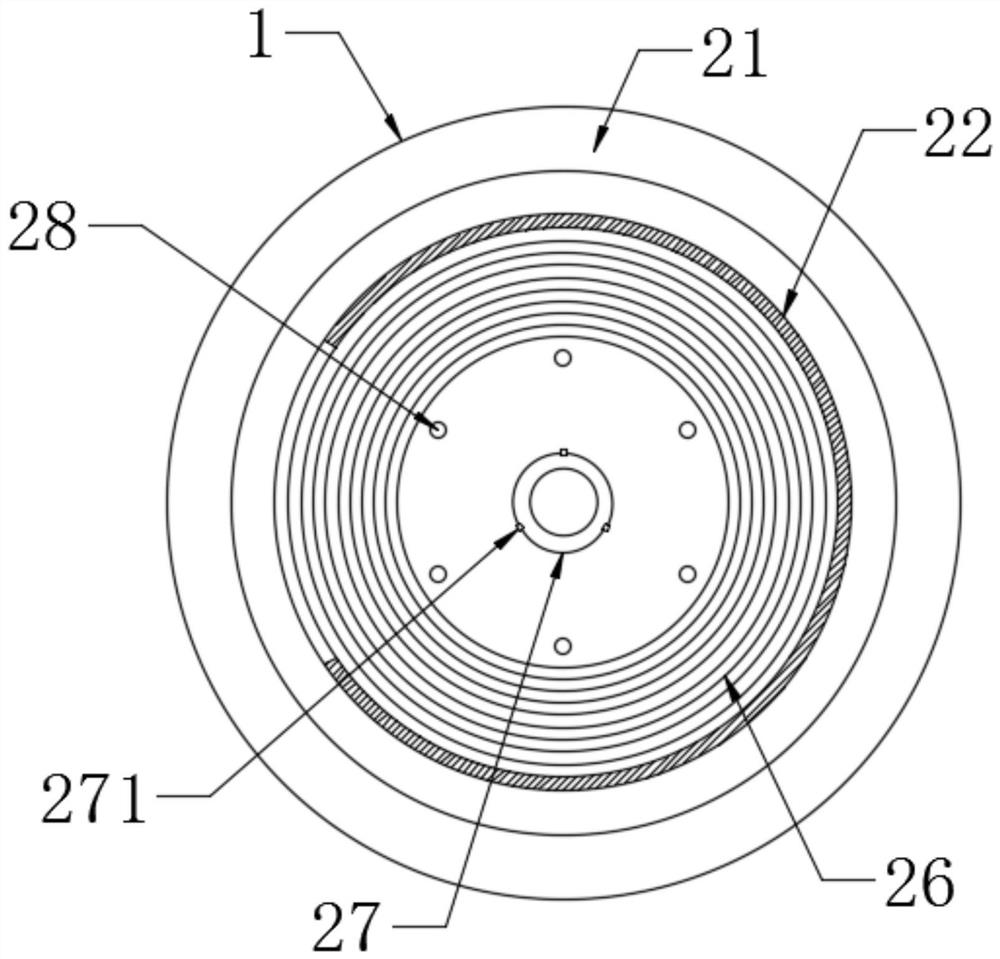
[0022] The rotor feeding mechanism 2 includes a bottom bracket 21, an embedded protection slide 22, a first buckle 23, a magnetic sheet 24, a second buckle 25, a matching groove 26, a bearing seat 27, a discharge jack 28, a rubber plug 221 and a label. Positive pin 271, bottom support 21 is installed on the left side of feeder main body 1, and bottom support 21 right end surface is provided with matching groove 26, and the right side of matching groove 26 is conn...


PUM


Abstract

The invention provides a permanent magnet linear synchronous motor feeding device, which comprises a bottom support, an embedded protection slip sheet, a first hasp, a magnetic sheet, a second hasp, a matching groove, a bearing seat, a discharge jack, a rubber bolt and a calibration pin, and is characterized in that the left side of a feeder main body is provided with the bottom support, the right end surface of the bottom support is provided with the matching groove, and the right side of the matching groove is connected with the embedded protection slip sheet; the rubber bolt is assembled on the left side of the embedded protection sliding sheet, the magnetic piece is assembled on the inner side of the annular side face of the embedded protection sliding sheet, the first hasp is assembled on the front side of the embedded protection sliding sheet, the second hasp is assembled on the front side of the embedded protection sliding sheet, the discharge jack is formed in the annular side face of the bottom support, the bearing seat is installed in the bottom support, and the calibration pin is assembled on the annular side face of the bearing seat. According to the design, the problem that an original permanent magnet linear synchronous motor rotor is difficult to install is solved, the structure is reasonable, the rotor can be conveniently and effectively fed and installed, and motor damage is prevented.

Description

technical field [0001] The invention is a permanent magnet linear synchronous motor feeding device, which belongs to the technical field of permanent magnet linear synchronous motors. Background technique [0002] In principle, the linear synchronous motor is exactly the same as the corresponding rotary synchronous motor. After the 1960s, it became important as a propulsion device for high-speed ground transportation and as a power for hoisting devices after the 1980s. Like a normal synchronous motor, it has a polyphase armature winding and a DC excited field. The excitation method of the DC magnetic field can be conventional, can also be excited by a superconductor excitation winding, and can also use a permanent magnet. Although in principle, the linear synchronous motor can be used as an armature moving type or a magnetic field moving type, but it seems that the latter type is more practical. [0003] When installing the rotor of permanent magnet linear synchronous mot...

Claims


Application Information

Patent Timeline
Patent Type & Authority Applications(China)
IPC IPC(8): H02K15/03H02K41/03
CPCH02K15/03H02K41/031
Inventor 环一军
Owner 环一军
Learn More