
Electronic load device and load module with heat dissipation function

A technology of electronic loads and load modules, applied in the modification of power electronics, circuits, electrical components, etc., can solve problems such as wasting resources, unable to reduce weight, and over-satisfying demands

Active Publication Date: 2021-05-18
致茂电子(苏州)有限公司
View PDF3 Cites 0 Cited by
  • Summary
  • Abstract
  • Description
  • Claims
  • Application Information

AI Technical Summary

Problems solved by technology

[0003] However, while reducing costs, the above approach also has some disadvantages
For example, when the heat dissipation structure that can be used for a 500-watt model is only used for a 100-watt or 300-watt model, the specifications are undoubtedly over-satisfied. burden
In addition, if the 100W or 300W model uses the heat dissipation structure of the 500W model, the volume of the 100W or 300W model will be too large, resulting in the weight being unable to be reduced

Method used


Image

  • Electronic load device and load module with heat dissipation function
  • Electronic load device and load module with heat dissipation function
  • Electronic load device and load module with heat dissipation function

Examples


Embodiment Construction

[0031] The aforementioned and other technical contents, features and effects of the present application will be clearly presented in the following detailed description of a preferred embodiment with reference to the accompanying drawings. The directional terms mentioned in the following embodiments, such as: up, down, left, right, front or back, etc., are only referring to the directions of the drawings. Accordingly, the directional terms used are for illustration and not for limitation of the application.

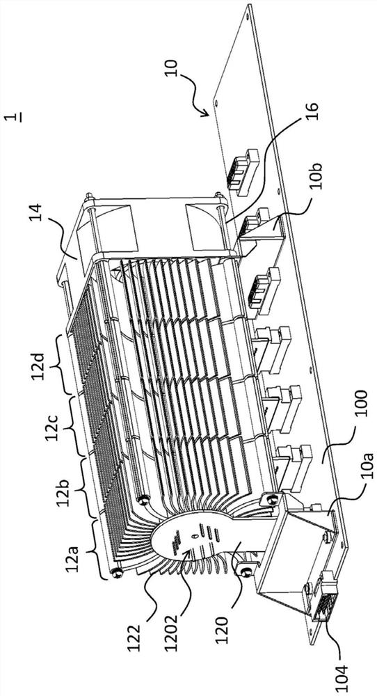
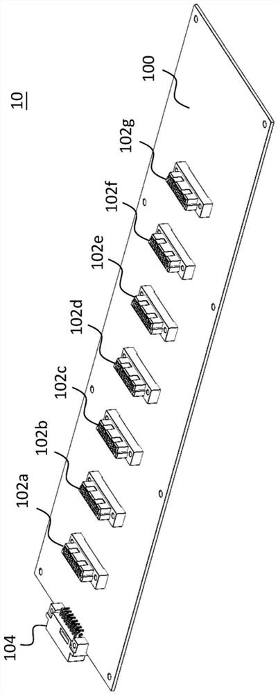
[0032] see figure 1 , figure 1 It is a three-dimensional schematic diagram illustrating an electronic load device according to an embodiment of the present application. Such as figure 1 As shown, the electronic load device 1 includes a main board 10 and a plurality of load modules 12a-12d, and a fan unit 14 may be connected to one side of the load module 12d. Here, although figure 1 Four load modules 12 a - 12 d are shown, but this embodiment does not limit the actual...


PUM


Abstract

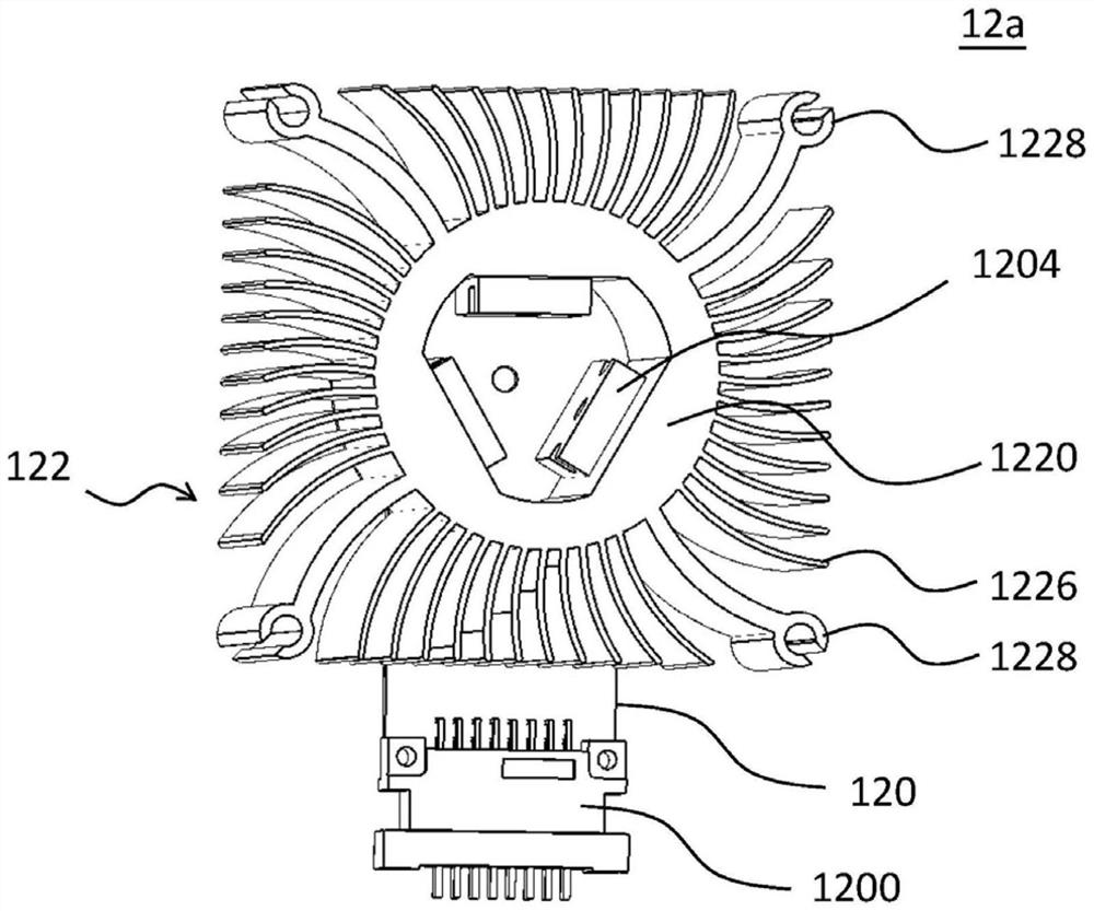
The invention provides an electronic load device and a load module with a heat dissipation function. The electronic load device comprises a mainboard and the load module. The mainboard is provided with a plurality of first ports, and the load module comprises a sub-board and a heat dissipation unit. The sub-board is provided with a second port and a pin slot, the second port is used for being connected with one of the plurality of first ports in a pluggable mode, and the pin slot is used for being connected with the power assembly. The heat dissipation unit is provided with a cylindrical body and a plurality of heat dissipation fins, the cylindrical body defines an outer surface and an inner surface opposite to the outer surface, and the heat dissipation fins are connected to the outer surface. When the power assembly is connected with the pin groove, the power assembly contacts the inner surface.

Description

technical field [0001] The present application relates to an electronic load device and a load module, in particular to a modularized electronic load device and a load module with heat dissipation function. Background technique [0002] In order to meet various usage scenarios and needs, the same series of products may have models with different performances. For example, the electronic load device may correspond to different models according to different load powers. Generally speaking, although the types of electronic load devices are different, in most cases there is only a difference in the number of power components, and the heat dissipation structure is often not designed separately, but a heat dissipation structure that can meet the highest load power is used. For example, assuming that the same series of electronic load devices needs to be designed with load powers of 500W, 300W and 100W, the industry tends to choose a heat dissipation structure with a specification...

Claims


Application Information

Patent Timeline
IPC IPC(8): H05K7/20
CPCH05K7/20136H05K7/20409H05K7/20163H05K7/20154H05K7/20909H01L23/3672
Inventor 黄建兴刘崇琳周建车
Owner 致茂电子(苏州)有限公司
Learn More