
Spiral oil pipe paraffin removal device

A helical, tubing technology, used in cleaning appliances, wellbore/well components, earth-moving drilling, etc., can solve the problems of poor timeliness, high cost, high energy consumption, etc., and achieve low cost, easy operation, and easy installation. Effect

Pending Publication Date: 2021-05-21
曹许明
View PDF0 Cites 0 Cited by
  • Summary
  • Abstract
  • Description
  • Claims
  • Application Information

AI Technical Summary

Problems solved by technology

This method has poor timeliness, large energy consumption and high cost

Method used


Image

  • Spiral oil pipe paraffin removal device
  • Spiral oil pipe paraffin removal device
  • Spiral oil pipe paraffin removal device

Examples


Embodiment 1

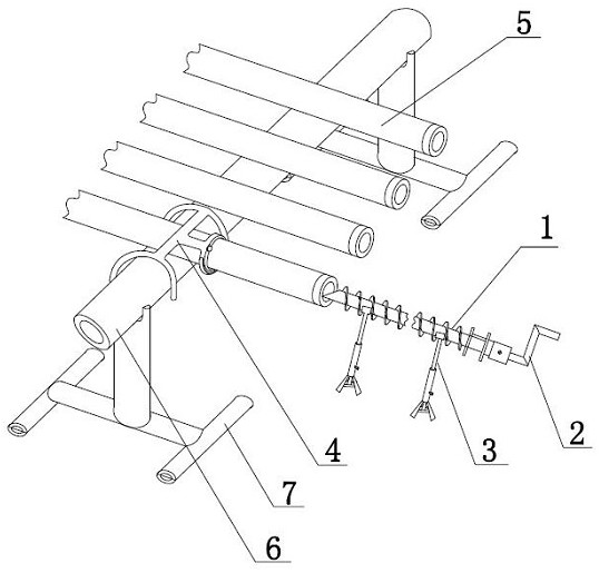
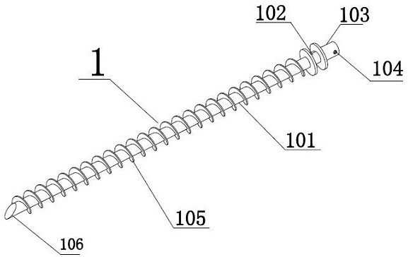
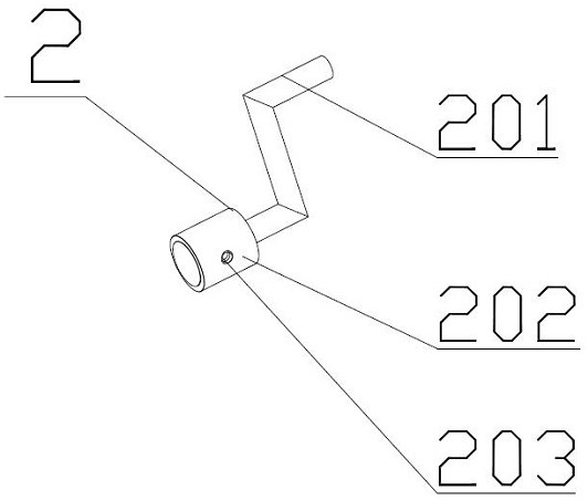
[0022] The oil pipe with an inner diameter of 62 mm has an oil rod with a diameter of 22 mm inside the pipe. When the wax deposition is serious, the thickness of the pipe wall reaches 20 mm. Figure 1-5 As shown, the spiral oil pipe wax removal device adopted in the present invention includes a wax scraper 1, a rocker 2, a support 3, a pipe gripper 4, a pipe bridge frame 6 and a pipe bridge stool 7, and the pipe bridge frame 6 is supported by the pipe bridge stool 7 , place the oil pipe 5 on the pipe bridge 6, fix the oil pipe 5 that needs wax removal with the pipe gripper 4, and set two downward U-shaped pipe clips 404 on the pipe gripper 4, use the pin shaft 403 and the clamp 401 is connected and fixed in one body, and the caliber of the U-shaped pipe clip 404 is smaller than that of the pipe bridge. Utilize the tension of the U-shaped pipe clip 404 to firmly fix the oil pipe 5 to be waxed on the pipe bridge frame 6, and then use the tight The hoop 401 locks the oil pipe 5 s...

Embodiment 2

[0028] The difference from Example 1 is that under normal circumstances, the length of the oil pipe 5 is different, and a longer wax scraper (1) is required, but the wax scraper 1 is too long and inconvenient to carry, so the wax scraper 1 can be made into Assemblies connected by multi-section detachable wax scraper nipple 1A, as attached figure 1 with 6 As shown, the sharpened part 106 of the wax scraper 1 is set on the short joint at the front end, and the short joint at the tail end is provided with a butt joint 103, which is fixedly connected with the crank handle 2, and one end of the short joint 1A of the wax scraper connected in the middle is provided with an outer Thread, the other end is provided with an internal thread, the other end of the wax scraper pup 1A with a sharpened portion 106 is provided with an internal thread, and the other end of the wax scraper pup 1A with a butt joint 103 is provided with an internal thread, detachable The wax scraper nipple 1A is t...


PUM


Abstract

The invention provides a spiral oil pipe paraffin removal device which comprises a paraffin scraper, a rocking handle, a support, a pipe clamping device, a pipe bridge frame and a pipe bridge stool, an oil pipe is fixed to the pipe bridge frame through the pipe clamping device, the pipe bridge frame is supported by the pipe bridge stool, the paraffin scraper is formed by welding a spiral scraping piece on a section of oil rod, a butt joint is arranged at one end of the oil rod, the other end of the oil rod is a sharpening part, a pin hole is formed in the butt joint, the rocking handle comprises a handle and a butt joint sleeve, the inner diameter of the butt joint sleeve is matched with the outer diameter of the butt joint of the oil rod, the pin hole is formed in the butt joint sleeve, a plurality of supports are arranged on the lower portion of the oil rod, a wax shoveling plate, a support base and a height adjustable device are arranged on the tops of the supports, the pipe clamping device is provided with two downward U-shaped pipe clamps which are fixedly connected with a tightening hoop into a whole through a pin shaft. The spiral oil pipe paraffin removal device is novel and flexible in structure, convenient to mount, dismount, carry and transport, low in cost, easy to operate, capable of being conveniently operated in a well site with limited space, high in efficiency, energy-saving and environmentally friendly.

Description

technical field [0001] The invention belongs to the technical field of oil well maintenance, and in particular relates to a spiral oil pipe wax removal device. Background technique [0002] During the production process of the oil well, the inner wall of the oil pipe will be waxed. The fundamental reason is that the crude oil produced by the oil well contains wax. There are two processes in oil well waxing. First, the wax is precipitated from the crude oil, and then it accumulates and adheres to the pipe wall. The wax that was originally dissolved in crude oil was condensed out during the mining process due to the decline in the solubility of crude oil to wax. When the composition, temperature, and pressure of the crude oil change, so that its solubility decreases, a part of the wax will be precipitated from the crude oil, resulting in wax deposition on the pipe wall. The wax removal method commonly used in the oilfield field is to use a wax removal vehicle to remove wax. ...

Claims


Application Information

Patent Timeline
Patent Type & Authority Applications(China)
IPC IPC(8): E21B37/02
CPCE21B37/02
Inventor 曹许明张国栋王子良宋建涛张洋慕彩霞白崇高尚强奥生慧张聪魏升召秦欢
Owner 曹许明
Learn More