
Four-group parallel inverter welding power supply control method and circuit

A technology of inverter welding power supply and control method, which is applied in the direction of welding equipment, manufacturing tools, arc welding equipment, etc., and can solve the problems of four groups of sub-circuit output current balance, frequency, pulse width, phase error, and enlarged circuit Problems such as output imbalance, to achieve stable output current, ensure output current, and improve reliability

Pending Publication Date: 2021-05-25
SHANGHAI HUGONG ELECTRIC WELDING MACHINE MFG
View PDF0 Cites 2 Cited by
  • Summary
  • Abstract
  • Description
  • Claims
  • Application Information

AI Technical Summary

Problems solved by technology

[0002] At present, the inverter welding power supply of four groups of parallel main circuits has two control methods. One is that the driving signals of the four groups of IGBTs are completely independent, and the current signal is sampled from the primary side of the transformer of each group of sub-circuits. According to the sampling current Size, control the maximum output current of each transformer within the rated value, in order to ensure the stability of the total output current, each sub-circuit needs to have a certain margin to ensure the normal output, there is a current sharing problem among the four groups of outputs; Independent driving signals may have errors in frequency, pulse width, and phase, which further increases the output imbalance of each sub-circuit; the other is that the driving signals of the four groups of IGBTs are completely synchronized, and the synchronous start and synchronous shutdown , the current signal is sampled from the primary side of the transformer of each group of sub-circuits, and the maximum current of the total output of the inverter welding power supply is controlled to be within the rated value according to the size of the sampled current. However, due to the difference of the IGBT tubes, the tube voltage of each IGBT tube The drop will be different, and the output current balance between the four groups of sub-circuits cannot be achieved, which reduces the reliability of the whole machine

Method used


Image

  • Four-group parallel inverter welding power supply control method and circuit
  • Four-group parallel inverter welding power supply control method and circuit

Examples


specific Embodiment 1

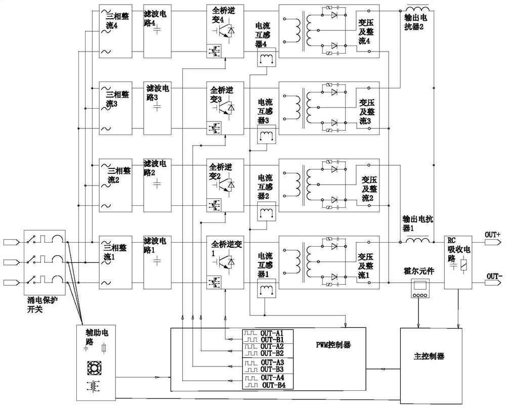
[0024] A four-group parallel inverter welding power supply circuit of the present application, such as figure 1 As shown, it includes a main controller, a PWM controller, an auxiliary circuit, and four sets of inverter sub-power supplies connected in parallel. The main controller is used to detect the output current of the whole power supply; each inverter sub-power supply includes a three-phase rectifier circuit connected in sequence , filter circuit, IGBT full-bridge inverter circuit, transformer and rectifier circuit, current detection circuit, the current detection circuit includes a current transformer, which is used to detect the inversion of each transformer and rectifier circuit input end, and IGBT full-bridge inverter circuit output To change the output current of the sub-power supply, the main controller is used to control the PWM controller to output four PWM signals that are independent of each other and whose rising edges are synchronous. A set of PWM signals is us...

specific Embodiment 2

[0045] According to a method for controlling four groups of parallel inverter welding power sources in the present application, the PWM controller outputs four groups of independent PWM control signals, each group of PWM control signals includes two PWM control signals with a phase difference of 180 degrees, and each PWM control signal It is used to drive the conduction or cut-off of the two IGBT tubes at the corresponding positions of the IGBT full-bridge inverter circuit.

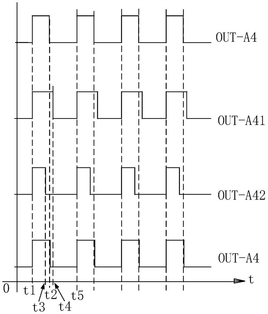
[0046] The main controller controls the rising edge synchronization of four independent PWM control signals, detects the output current of each inverter sub-power supply, compares the output current of each inverter sub-power supply with the current set value, and controls the falling edge of each PWM signal. At the time of shutdown, reduce the PWM signal duty cycle of the inverter sub-power supply with large output current, increase the PWM signal duty cycle of the inverter sub-power supply with small out...


PUM


Abstract

The invention discloses a four-group parallel inverter welding power supply control method and circuit. The four-group parallel inverter welding power supply comprises a main controller, a PWM controller and four groups of inverter sub-power supplies connected in parallel, wherein each inverter sub-power supply comprises a three-phase rectification circuit, a filter circuit, an IGBT full-bridge inverter circuit, a transformation and rectification circuit and a current detection circuit which are connected in sequence; the PWM controller outputs four groups of independent PWM control signals to the four groups of IGBT full-bridge inverter circuits respectively; rising edges of the four paths of PWM control signals are synchronous; output current of each inverter sub-power supply is detected; the output current of each inverter sub-power supply is compared with a current set value; the output currents of the inverter sub-power supplies are compared; and the turn-off time of the falling edge of each PWM signal is controlled, the duty ratio of the PWM signal of the inverter sub-power supply with large output current is reduced, the duty ratio of the PWM signal of the inverter sub-power supply with small output current is increased, the output currents of the inverter sub-power supplies are equal, and the reliability of the welding power supply is improved.

Description

technical field [0001] The invention relates to the technical field of inverter welding power supply control, in particular to a four-group parallel inverter welding power supply control method and circuit. Background technique [0002] At present, the inverter welding power supply of four groups of parallel main circuits has two control methods. One is that the driving signals of the four groups of IGBTs are completely independent, and the current signal is sampled from the primary side of the transformer of each group of sub-circuits. According to the sampling current Size, control the maximum output current of each transformer within the rated value, in order to ensure the stability of the total output current, each sub-circuit needs to have a certain margin to ensure the normal output, there is a current sharing problem among the four groups of outputs; Independent driving signals may have errors in frequency, pulse width, and phase, which further increases the output im...

Claims


Application Information

Patent Timeline
Patent Type & Authority Applications(China)
IPC IPC(8): B23K9/10B23K9/095
CPCB23K9/095B23K9/1043
Inventor 舒振宇黄叶剑
Owner SHANGHAI HUGONG ELECTRIC WELDING MACHINE MFG
Learn More