Clamping mechanism for full-automatic internal polishing machine

A clamping mechanism and internal polishing technology, which is applied to surface polishing machine tools, machine tools suitable for grinding the edge of workpieces, and parts of grinding machine tools. and other issues, to achieve a high degree of automation, reduce the labor intensity of workers, and improve production efficiency

Pending Publication Date: 2021-05-25
中寰(山东)重工机械有限公司
View PDF0 Cites 0 Cited by
  • Summary
  • Abstract
  • Description
  • Claims
  • Application Information

AI Technical Summary

Problems solved by technology

The traditional method is generally completed by high-pressure sandblasting and washing, but the shortcomings of this traditional washing and rust removal method are that rust removal and polishing are not thorough, and there are also simple equipment, low degree of automation, serious pollution, labor Insufficient strength, etc.; Another method is to put steel grit into the workpiece, and drive the workpiece through mechanical transmission to shake the bottle bottom and bottle mouth left and right while rotating, so that the steel grit will rub against the inner wall of the workpiece to achieve rust removal and polishing. purpose, but this method has the disadvantages of high equipment energy consumption, high labor intensity for upper and lower sand materials, low polishing efficiency, large vibration, and large noise.
Although someone has invented a clamping device that can fix the workpiece for sandblasting and polishing, the current clamping device can only simply clamp and fix the workpiece, which is inconvenient to realize the attitude adjustment of the workpiece, such as loading it in a horizontal posture, and then Through the cooperation of other mechanisms, the workpiece can be erected to facilitate subsequent polishing operations
At the same time, the existing clamping equipment is not easy to realize the autonomous rotation of the workpiece, which leads to a long time consumption in the process of loading, unloading and polishing, and requires more manpower assistance

Method used


Image

  • Clamping mechanism for full-automatic internal polishing machine
  • Clamping mechanism for full-automatic internal polishing machine
  • Clamping mechanism for full-automatic internal polishing machine

Examples


Embodiment Construction

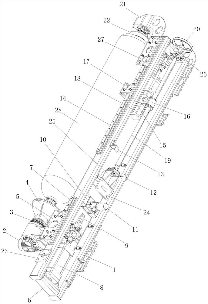
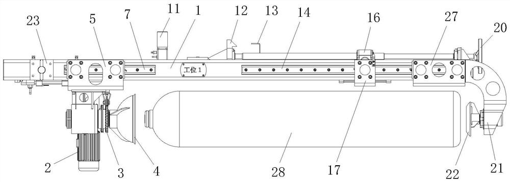
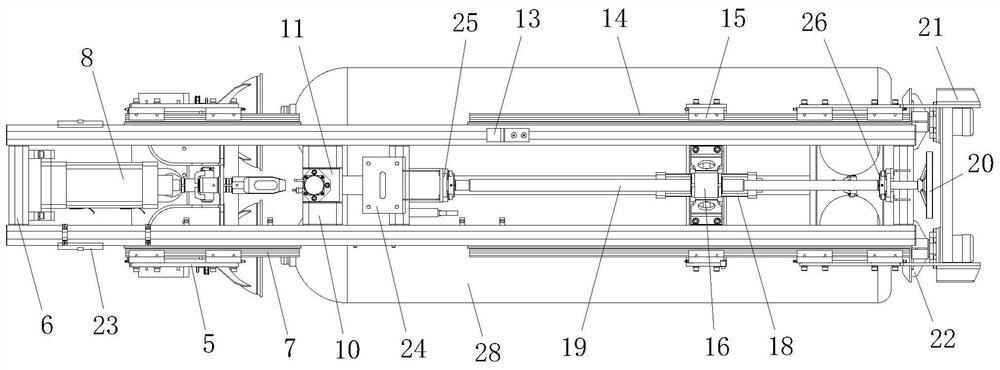
[0022] The present invention will be further described below in conjunction with accompanying drawing by specific embodiment:

[0023] In this example, refer to Figure 1-Figure 5 , the clamping mechanism for a full-automatic internal polishing machine includes a main support frame 1, a rotating motor 2, a rotating tray 4, a propulsion cylinder 8, a compression cylinder 18 and a rear end compression mechanism, and the main support frame 1 Two clamping stations are arranged on the top so that two workpieces 28 can be clamped at the same time; Connect, push the rotary tray 4 and the compression cylinder 18 to push the rear end pressing mechanism through the propulsion cylinder 8, so that the rotating tray 4 and the rear end pressing mechanism respectively press the front and rear ends of the workpiece 28 to realize the clamping of the workpiece 28; The rotating pallet 4 is connected with the rotating motor 2 to form a driving structure for the rotation of the workpiece 28 itsel...


PUM


Abstract

The invention discloses a clamping mechanism for a full-automatic internal polishing machine. The clamping mechanism comprises a main supporting frame, a rotating motor, rotating trays, a propelling air cylinder, a pressing air cylinder and rear end pressing mechanisms. Two clamping stations are arranged on the main supporting frame. Each clamping station comprises one rotating tray and one rear end pressing mechanism, wherein the rear end pressing mechanisms are connected with the pressing air cylinder. The rotating trays are connected with the rotating motor. The rotating motor, the propelling air cylinder and the pressing air cylinder are installed on the main supporting frame. According to the clamping mechanism, the rotating trays are matched with the propelling air cylinder, and a rear end pressing head is matched with the pressing air cylinder, so that workpieces are pressed and fixed; and meanwhile, the rotating trays are matched with the rotating motor, and the workpieces can spin when pressed under the cooperation of the rotatable rear end pressing head, so that the two workpieces can work continuously at the same time conveniently, the automation degree is high, the production efficiency is greatly improved, and the labor intensity of workers is relieved.

Description

technical field [0001] The invention relates to the technical field of polishing equipment accessories, in particular to a clamping mechanism applied to internal polishing equipment. Background technique [0002] Circular metal-like products with inner cavities are widely used in various industries. Such products need to be polished on their inner walls to remove rust, stains, etc. on the inner walls. Whether effective rust removal can be achieved can be said to be the The core of product quality control. The traditional method is generally completed by high-pressure sandblasting and washing, but the shortcomings of this traditional washing and rust removal method are that rust removal and polishing are not thorough, and there are also simple equipment, low degree of automation, serious pollution, labor Insufficient strength, etc.; Another method is to put steel grit into the workpiece, and drive the workpiece through mechanical transmission to shake the bottle bottom and b...

Claims


Application Information

Patent Timeline
Patent Type & Authority Applications(China)
IPC IPC(8): B24B27/033B24B31/00B24B31/12B24B41/06B24B47/12B24B47/00
CPCB24B27/033B24B31/006B24B31/12B24B41/061B24B47/00B24B47/12
Inventor 李金龙何激淼徐坚张朝营巴忠辉
Owner 中寰(山东)重工机械有限公司
Why Eureka
Try Eureka