Rotation control structure for wafer transfer robot

A technology of handling robots and control structures, applied in the direction of program control manipulators, manipulators, manufacturing tools, etc., can solve the problems that the products cannot meet the requirements of actual use, there is no relatively mature design method, and the development level of wafer handling robots is restricted. Achieve the effect of improving space utilization, compact design structure, improving stability and reliability

Pending Publication Date: 2021-05-25
昀智科技(北京)有限责任公司
View PDF0 Cites 0 Cited by
  • Summary
  • Abstract
  • Description
  • Claims
  • Application Information

AI Technical Summary

Problems solved by technology

At present, domestic technical research in this area starts relatively late, similar products cannot meet the requirements of actual use, and there is no relatively mature design method, which is also one of the main reasons restricting the development level of domestic wafer handling robots.

Method used


Image

  • Rotation control structure for wafer transfer robot
  • Rotation control structure for wafer transfer robot
  • Rotation control structure for wafer transfer robot

Examples


Embodiment Construction

[0057] Embodiments of the present disclosure will be described in detail below in conjunction with the accompanying drawings.

[0058]Embodiments of the present disclosure are described below through specific examples, and those skilled in the art can easily understand other advantages and effects of the present disclosure from the contents disclosed in this specification. Apparently, the described embodiments are only some of the embodiments of the present disclosure, not all of them. The present disclosure can also be implemented or applied through different specific implementation modes, and various modifications or changes can be made to the details in this specification based on different viewpoints and applications without departing from the spirit of the present disclosure. It should be noted that, in the case of no conflict, the following embodiments and features in the embodiments can be combined with each other. Based on the embodiments in the present disclosure, al...


PUM


Abstract

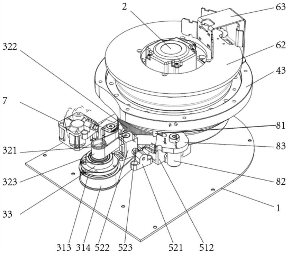
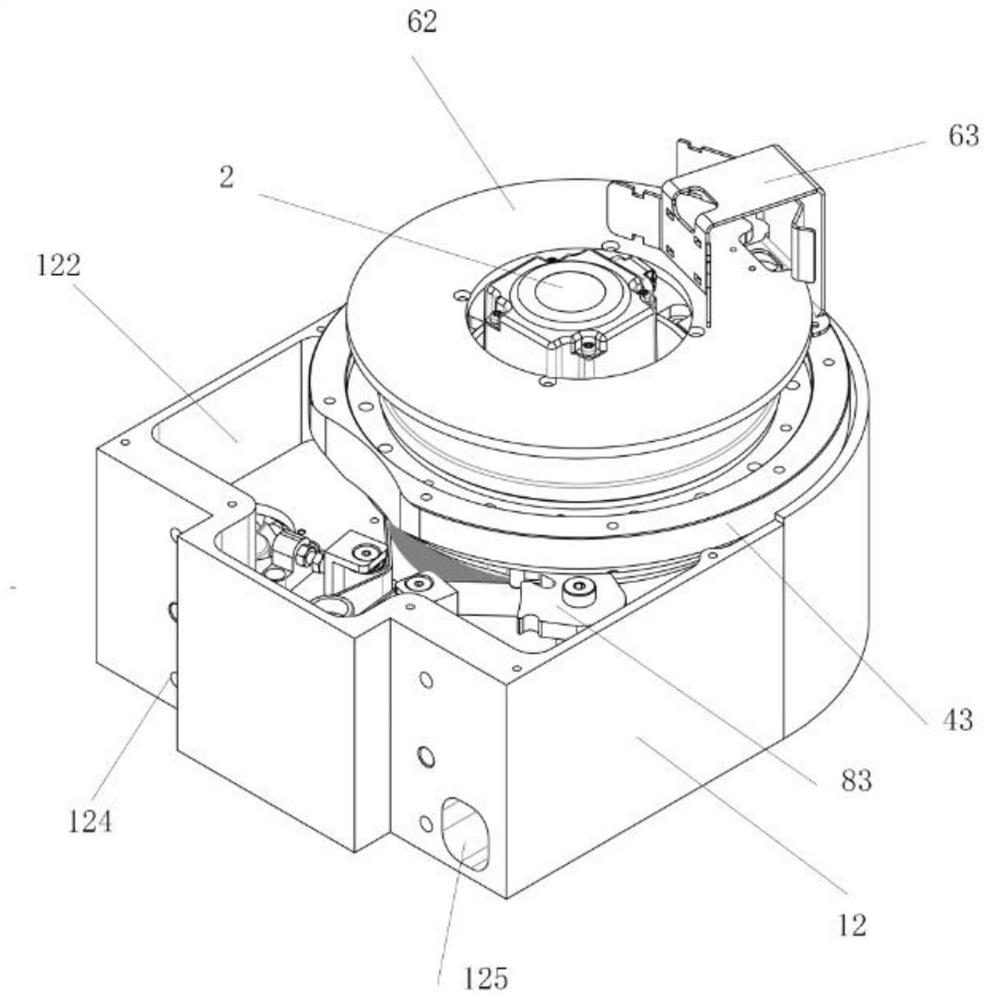
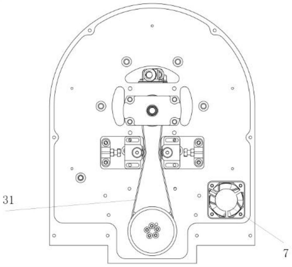
The invention discloses a rotation control structure for a wafer transfer robot. The rotation control structure comprises a supporting structure, a driving structure, a transmission structure and a rotating structure; the supporting structure comprises a bottom plate, a base and a panel, the base is of a hollow cavity structure with a top opening and a bottom opening, a partition plate is arranged on the inner wall of the base and divides the base into a top-layer base body and a bottom-layer base body, and the panel and the bottom plate are installed on the base; the driving structure penetrates through the rotating structure and is mounted on the base; the transmission structure is mounted on the base and comprises a first transmission structure, a second transmission structure and a connecting shaft; the connecting shaft is rotationally connected to the base; the first transmission structure is located in the bottom-layer base body and fixedly connected with the bottom end of the connecting shaft and the driving structure; and the second transmission structure is located in the top-layer base body and fixedly connected with the top end of the connecting shaft and the rotating structure. The transmission mechanisms are arranged on the top layer and the bottom layer of the base and fixedly connected with the connecting shaft, so that the device is compact in structure, small in occupied space and good in control precision and movement stability.

Description

technical field [0001] The invention relates to the technical field of semiconductor manufacturing, in particular to a rotation control structure for a wafer handling robot. Background technique [0002] The rotation structure in the wafer handling robot is mainly to control the rotation angle of the robot in the horizontal direction, and the stability and precision of its motion control are affected by the weight and structure of the upper load. With the widespread application of large-size wafers and the use of multi-functional grippers, the overall structure of the wafer handling robot is more complex, the volume increases, and the weight increases, thus affecting the load capacity, control accuracy and motion stability of the rotating shaft. Higher design requirements are put forward, and the rotating structure should also meet the requirements for installation and use in high-level ultra-clean environments. At present, domestic technical research in this area starts re...

Claims


Application Information

Patent Timeline
Patent Type & Authority Applications(China)
IPC IPC(8): B25J9/00B25J19/00B25J11/00
CPCB25J9/0009B25J11/0095B25J19/00B25J19/0058
Inventor 何瑞郭梅刘丹韩浚源
Owner 昀智科技(北京)有限责任公司
Why Eureka
Try Eureka