Light transmission device punching equipment for vehicle-mounted microscope

A technology of punching equipment and light-passing device, which is applied in metal processing and other directions, can solve problems such as occurrence of errors and affecting the use of light-passing device.

Active Publication Date: 2021-05-25
上饶市鑫锐光电有限公司
View PDF12 Cites 2 Cited by
  • Summary
  • Abstract
  • Description
  • Claims
  • Application Information

AI Technical Summary

Problems solved by technology

[0004]In order to overcome the shortcoming of manual punching of the shutter, which will easily cause errors and affect the use of the shutter if the time is too long, the technical problem to be solved is: to provide A light-passer punching device for a vehicle-mounted microscope that automatically punches holes, reduces manual punching errors, and is easy to operate

Method used


Image

  • Light transmission device punching equipment for vehicle-mounted microscope
  • Light transmission device punching equipment for vehicle-mounted microscope
  • Light transmission device punching equipment for vehicle-mounted microscope

Examples


Embodiment 1

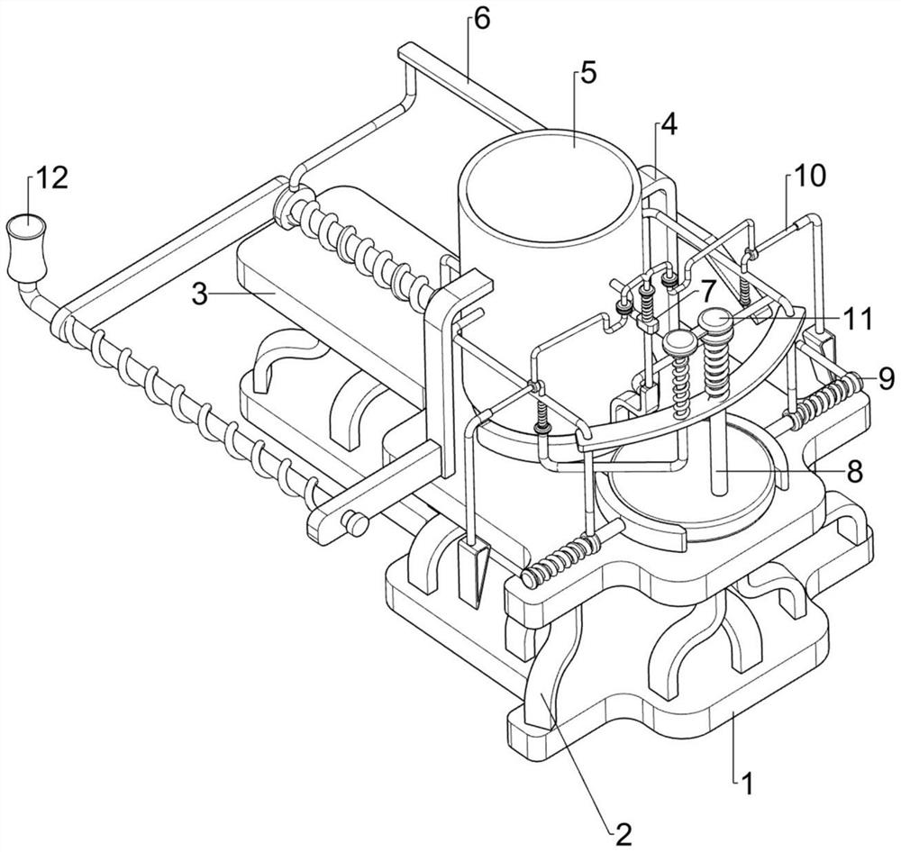
[0065]Car microscope lightner punching equipment, such asfigure 1 As shown, including the first support plate 1, the first support frame 2, the second support plate 3, the second support frame 4, the discharge frame 5, the push mechanism 6, the opening and joint mechanism 7, the punching mechanism 8 and the clip. Tight mechanism 9, the first support plate 1 is provided with a first support frame 2, and a second support plate 3 is provided at the top of the first support frame 2, and the second support plate 3 is provided with a second support frame 4 at the top of the second support plate 3. A discharge frame 5 is provided between the second support frames 4 on both sides, and a push mechanism 6 is provided in the lower left side of the discharge frame 5, and the upper right upper right side of the discharge frame 5 is provided with an opening and closing mechanism 7. A punching mechanism 8 is provided in the outer middle, and a clamping mechanism 9 is provided on the lower right si...

Embodiment 2

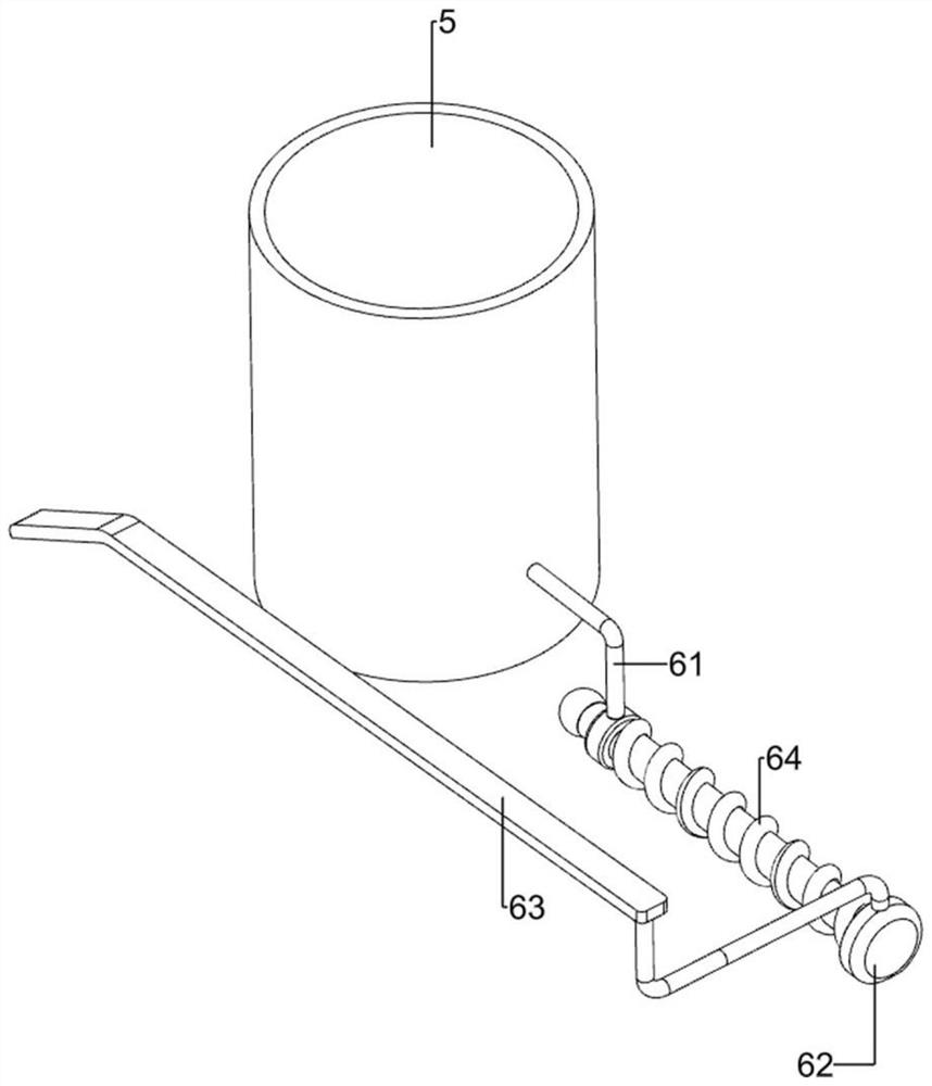
[0068]On the basis of Example 1, such asFigure 2- Figure 5 As shown, the pirate mechanism 6 includes a third support frame 61, a pincer 62, a first long block 63, and a first spring 64, and the outer upper left side of the discharge frame 5 is provided with a third support frame 61, the third support. The rack 61 is slid in the upper left side sliding pins 62, and the first long block 63 is provided on the left side of the pincedule 62, and the pincer 62 is surrounded by the first spring 64, the first spring 64 and the first respectively. The long block 63 and the third support frame 61 are connected.

[0069]In the discharge box 5, it is then manually pushed to the right movement, so that the pins 62 is moved to the right, and the first spring 64 is compressed, the pusher 62 is right Movement can introduce the lightner, realize the effect of the push, when people release, the first spring 64 resets the throttle 62 to move to the left, so that the first long block 63 is reset to the le...

Embodiment 3

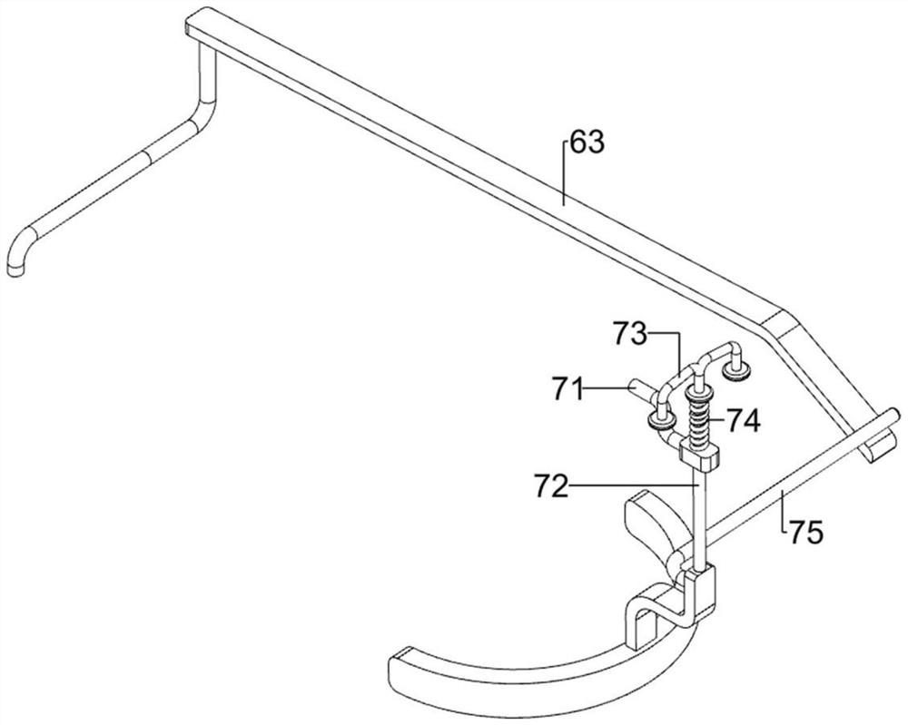
[0077]On the basis of Example 2, such asFigure 6 - Figure 8The first auxiliary mechanism 10 is further included, the first auxiliary mechanism 10 includes a first clip rod 101, a fifth spring 102, and a second circumferential rod 103, and the bottom side of the first round block 73 is sided. The second round block 103, the lower portion of the second round block 103 is provided with a first clip rod 101, and the first clip rod 101 is fitted with the second cylindrical rod 93, and the first counter rod 101 is slidoff. Connect, the inner lower portion of the first clip rod 101 is wound around the fifth spring 102, and the fifth spring 102 is connected to the first clip rod 101 and the first fixing lever 81, respectively.

[0078]When the first circumferential rod 73 moves upward, the first circumferential rod 73 drives the second round block rod 103 to move upward, the fifth spring 102 is compressed, so that the first club 101 is slid, the first club 101 is When the second cylindrical ro...


PUM


Abstract

The invention relates to punching equipment, in particular to light transmission device punching equipment for a vehicle-mounted microscope. According to the light-transmitting device punching equipment for the vehicle-mounted microscope, automatic punching is achieved, manual punching errors are reduced, and operation is convenient. The light transmission device punching equipment for the vehicle-mounted microscope comprises a first supporting plate, first supporting frames arranged on the first supporting plate, a second supporting plate arranged between the tops of the first supporting frames, second supporting frames arranged at the tops of the two sides of the middle of the second supporting plate, and a discharging frame arranged between the second supporting frames at the two sides. According to the light transmission device punching equipment, a first long block frame is manually pushed to move rightwards, so that a pusher is driven to move rightwards, a first spring is compressed, the pusher moves rightwards to push out a light transmission device, and the material pushing effect is achieved.

Description

Technical field[0001]The present invention relates to a punching apparatus, and more particularly to an in-vehicle microscope aperture device.Background technique[0002]The microscope is an optical instrument consisting of a combination of a lens or several lenses. It is mainly used to enlarge the microscopic object to become the instrument you can see by human eye. The microscope helps scientists find new species, which helps doctors to treat diseases. It can be used for biological, pharmaceutical, microscopic particles, etc., the light object is close to the stage, which can make a circular rotation, adjust the strength of the light, change the brightness of the field, easy to observe, current, microscope manufacturing Factory is usually manually punched, which is not suitable for puncturing holes for a long time, and the time is too long. It affects the use of the light object.[0003]In view of the above circumstances, we need to design an automatic punching, reducing artificial pu...

Claims


Application Information

Patent Timeline
Patent Type & Authority Applications(China)
IPC IPC(8): B26F1/16B26D7/02
CPCB26F1/16B26D7/02
Inventor 刘申
Owner 上饶市鑫锐光电有限公司
Why Eureka
Try Eureka