Traction robot and traction equipment
A traction equipment and robot technology, applied in the traction field, can solve the problems of poor traction reliability, high bearing performance requirements, and large power consumption, and achieve the effects of improving reliability, improving comprehensive traction performance, and reducing power consumption.
- Summary
- Abstract
- Description
- Claims
- Application Information
AI Technical Summary
Problems solved by technology
Method used
Image

Examples
Embodiment 1
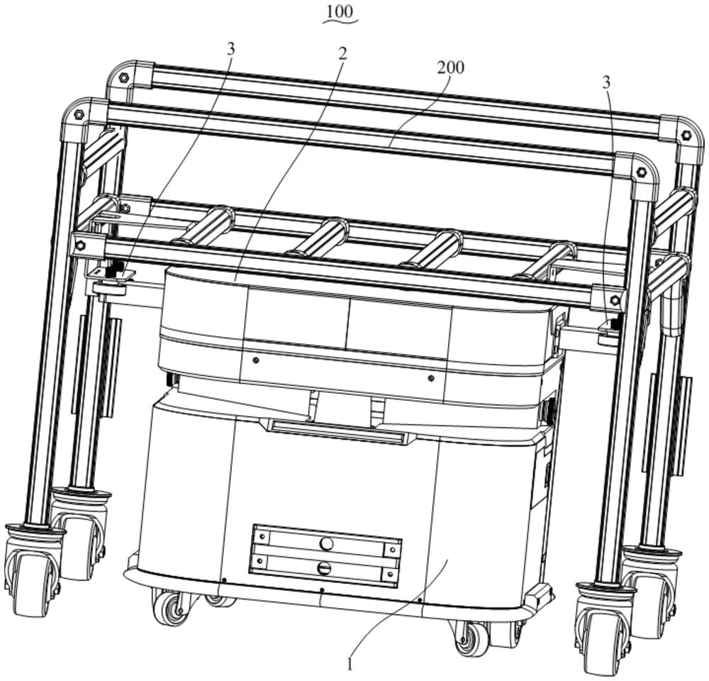
[0073] Figure 1 to Figure 8 What is shown is a schematic structural view of the traction robot 100 and the traction device 1000 provided in this embodiment.
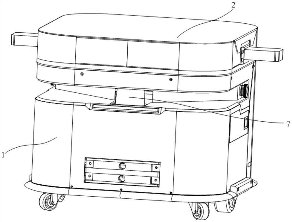
[0074] see Figure 1 to Figure 3 , the traction robot 100 includes an automatic guided vehicle 1 and a traction device 2 , and the traction device 2 is installed on the automatic guided vehicle 1 . By installing the towing device 2 on the automatic guided vehicle 1 , it can be used to tow the material carrier 200 with the locking structures 3 on opposite sides, and carry the material carrier 200 to move.
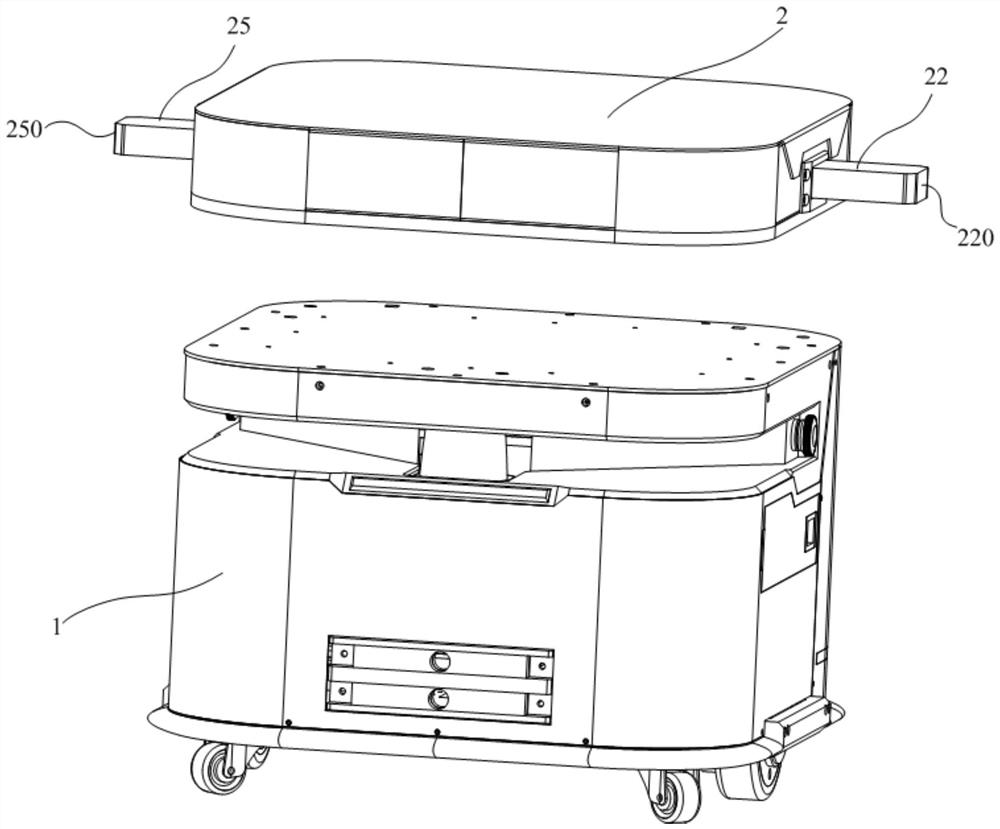
[0075] see image 3 , Figure 4 and Figure 5 The traction device 2 includes a device main body 20, a first guide 21, a first moving connector 22, a first connecting rod 23, a second guiding member 24, a second moving connector 25, a second connecting rod 26, a first A moving part 27 and a driving mechanism 28 . Wherein, the driving mechanism 28 is arranged on the device main body 20 or on the automatic guided v...
Embodiment 2
[0093] see Figure 1 to Figure 10 and Figure 11 The difference between this embodiment and the first embodiment mainly lies in the structure of the first kinematic connector 22 and the second kinematic connector 25 and the connection positions of the first connecting rod 23 and the second connecting rod 26 . In the first embodiment, the first moving connector 22 includes a first slider 221 slidably connected to the first guide 21 and a first clip 222 installed on the first slider 221 , and the first connecting rod 23 One end of one end is rotationally connected with the first card inserter 222; the second motion inserter 25 includes a second slide block 251 that is slidably connected with the second guide member 24 and a second card insert 252 installed on the second slide block 251, and One end of the second connecting rod 26 is rotatably connected with the second card insert 252 . In this embodiment, the first moving connector 22 is a first slider 221 that is slidably con...
Embodiment 3
[0096] see Figure 1 to Figure 10 and Figure 11 , The difference between this embodiment and Embodiment 1 and Embodiment 2 mainly lies in that the structure of the first moving member 27 is different. In Embodiment 1 and Embodiment 2, only the driving mechanism 28 needs to drive the first moving member 27 to make a linear reciprocating motion along the direction of the first trajectory MN to realize the functions of the present invention. In this embodiment, the traction device 2 also includes a third guide 29, the third guide 29 is arranged on the main body 20 of the device and is arranged on the side of the first track MN, and the third guide 29 is aligned with the first track MN. In parallel, the first moving part 27 is slidably connected with the third guide part 29 . In some possible implementations, there are two third guide members 29, and the two third guide members 29 are respectively arranged on opposite sides of the first track MN, which can improve the stability...
PUM
 Abstract
Description
Claims
Application Information
 - R&D
- Intellectual Property
- Life Sciences
- Materials
- Tech Scout
- Unparalleled Data Quality
- Higher Quality Content
- 60% Fewer Hallucinations
Browse by: Latest US Patents, China's latest patents, Technical Efficacy Thesaurus, Application Domain, Technology Topic, Popular Technical Reports.
© 2025 PatSnap. All rights reserved.Legal|Privacy policy|Modern Slavery Act Transparency Statement|Sitemap|About US| Contact US: help@patsnap.com