Pipeline installation support for electromechanical equipment

A pipeline installation, electromechanical equipment technology, applied in the direction of pipeline support, mechanical equipment, pipe components, etc., can solve the problems of inconvenience, increase of pipeline support fixing, power failure, etc., to improve the use value and space utilization rate, increase scalability performance, improve the effect of structural stability

Active Publication Date: 2021-05-25
ZHUZHOU CSR TIMES ELECTRIC CO LTD
View PDF9 Cites 0 Cited by
  • Summary
  • Abstract
  • Description
  • Claims
  • Application Information

AI Technical Summary

Problems solved by technology

However, the pipeline supports currently used in the market still have some deficiencies in the actual use process. 1. When shaking occurs, the pipes on the pipeline support will shake together, and when the amplitude is too strong, the pipes will fall off and bend. It may even cause the internal circuit to break and cause a power outage.
2. When fixing the pipeline, it is necessary to replace the pipeline clamp of the corresponding size according to the thickness of the pipeline, which is more troublesome to operate
3. The current pipeline support is generally set up before the pipeline is laid. The pipeline support is installed first, and then the pipeline is passed through the pipeline support to complete the fixation. For some lines that have completed the pipeline layout, it is inconvenient to increase the fixing of the pipeline support.

Method used


Image

  • Pipeline installation support for electromechanical equipment
  • Pipeline installation support for electromechanical equipment
  • Pipeline installation support for electromechanical equipment

Examples


Embodiment Construction

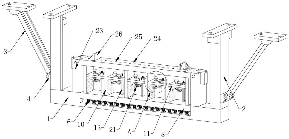
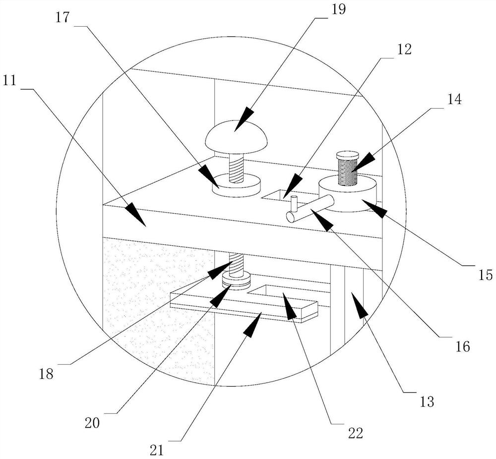
[0026] Such as Figure 1-7 As shown, the present invention includes a bracket main body, a mounting plate 8 and a limiting part, the mounting plate 8 is slidably arranged on the bracket main body, a plurality of shock absorbing spring rods 6 are arranged between the mounting plate 8 and the bracket main body, and the mounting plate 8 A plurality of baffles 10 are arranged along the length direction, and the limiting parts are arranged between the baffles 10. The limiting parts include a support plate 11 connected with the baffles 10 and a Y-axis limiting assembly arranged on the support plate 11 And X-axis limit components.

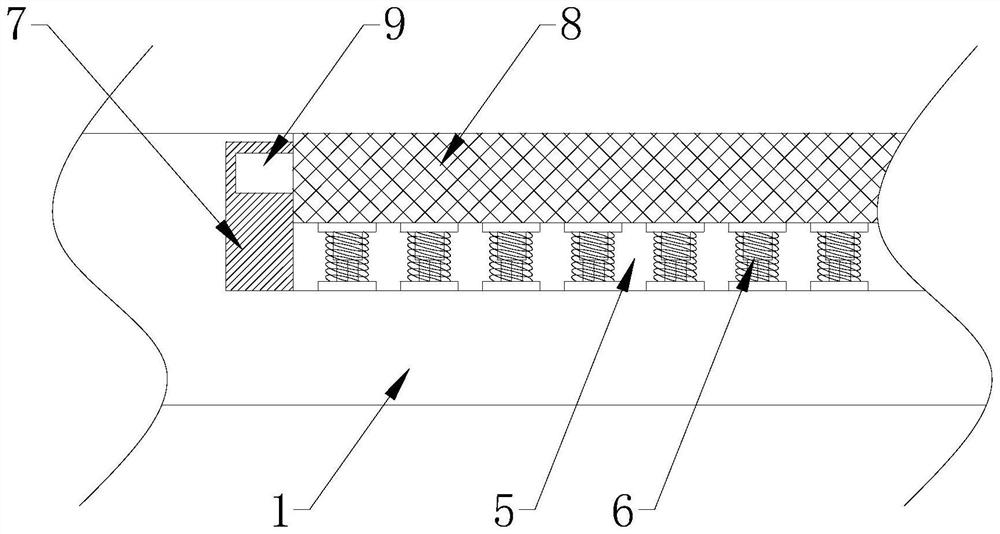
[0027] Such as figure 2 As shown, the crossbeam 1 of the main body of the bracket is provided with a groove 5 for installing the shock absorbing spring rod 6, and both sides of the groove 5 are provided with vertical chute 7 for the sliding of the mounting plate 8, and the vertical chute 7 is arranged on both sides of the mounting plate 8. The 7 projec...


PUM


Abstract

The invention belongs to an installation support, and particularly relates to a pipeline installation support for electromechanical equipment. The pipeline installation support comprises a support body, an installation plate and limiting components; the installation plate is arranged on the support body in a sliding mode; a plurality of damping spring rods are arranged between the installation plate and the support body; a plurality of partition plates are arranged on the installation plate in the length direction; the limiting components are arranged between the partition plates; the limiting component comprise supporting plates connected with the partition plates, Y-axis limiting assemblies and X-axis limiting assemblies; and the Y-axis limiting assemblies and X-axis limiting assemblies are arranged on the supporting plates. The damping spring rods are arranged between the support body and the installation plate, when vibration is generated at an installation position, the vibration is transmitted to the damping spring rods along with the support body, and the influence of vibration on a pipeline is reduced; meanwhile, the plurality of partition plates are arranged, multiple sets of pipelines can be arranged between the partition plates, the pipelines can be conveniently arranged and classified, the Y-axis limiting assemblies and the X-axis limiting assemblies are arranged on the partition plates, pipelines of different sizes can be stably clamped, and pipe clamps of different types do not need to be replaced.

Description

technical field [0001] The invention belongs to a mounting bracket, in particular to a pipeline mounting bracket for electromechanical equipment. Background technique [0002] During the installation process of mechanical and electrical equipment, there will often be problems of cross-coordination and mutual cooperation with civil engineering, process pipelines, electrical and other specialties, and it must be carried out with the progress of these professional constructions. Once the construction cooperation is not good, there will be rework, delays, etc. Phenomenon. [0003] The application of brackets is extremely wide, and can be seen everywhere in work and life. Pipeline brackets refer to a structural component used to support overhead laying pipelines on the ground. Divided into fixed brackets, sliding brackets, guide brackets, rolling brackets, etc. Pipeline supports are used wherever pipelines are laid. However, the pipeline supports currently used in the market s...

Claims


Application Information

Patent Timeline
Patent Type & Authority Applications(China)
IPC IPC(8): F16L3/223F16L55/035H02G3/04
CPCF16L3/223F16L55/035H02G3/04
Inventor 刘翰辞解培金胡平陈超录
Owner ZHUZHOU CSR TIMES ELECTRIC CO LTD
Why Eureka
Try Eureka