A high-efficiency water distribution nozzle for cooling towers

A technology for distributing sprinklers and cooling towers, which is used in water shower coolers, heat exchange equipment, lighting and heating equipment, etc., can solve the problem that the sputtering range cannot meet the design requirements, the sputtering range of the cooling sprinkler is narrowed, and the uniform distribution cannot be carried out. Water and other problems, to achieve the effect of maintaining the impact force, maintaining the sputtering range, and increasing the water pressure

Active Publication Date: 2022-04-26
XIAMEN JINMING ENERGY SAVING TECH
View PDF13 Cites 0 Cited by
  • Summary
  • Abstract
  • Description
  • Claims
  • Application Information

AI Technical Summary

Problems solved by technology

[0004] 1) The splash baffle is fixed. When the cooling water flow rate is small, that is, the water outlet pressure is low, the splash range cannot meet the design requirements;
[0005] 2) The inlet pressure of the cooling water depends entirely on the pressure at the inlet pipe end. When the pressure at the water inlet pipe end is low, the spraying range of the cooling nozzle is reduced, making it impossible to distribute water evenly, which directly affects the energy efficiency of the air conditioning system and increases the System energy consumption

Method used


Image

  • A high-efficiency water distribution nozzle for cooling towers
  • A high-efficiency water distribution nozzle for cooling towers
  • A high-efficiency water distribution nozzle for cooling towers

Examples


Embodiment Construction

[0031] In order to facilitate the understanding of those skilled in the art, the structure of the present invention will be further described in detail with the embodiments in conjunction with the accompanying drawings:

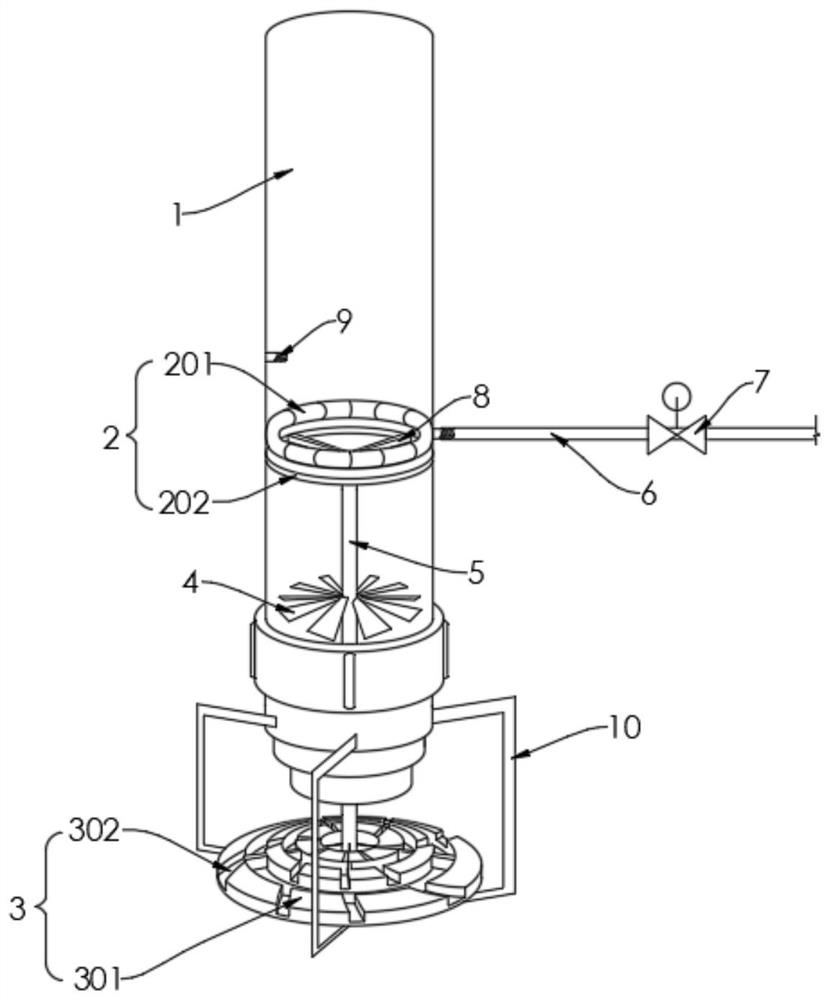
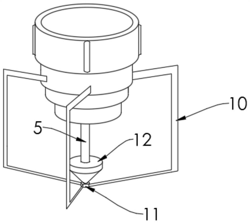
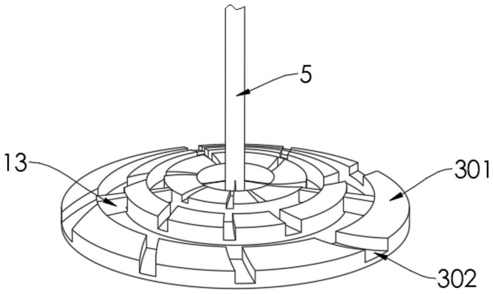
[0032] refer to Figure 1-3 , a high-efficiency water distribution nozzle for cooling towers, including

[0033] Water distribution pipe 1;

[0034] The water pressure regulating mechanism 2 includes a reinforcing ring plate 202 fixed on the inner wall of the water distribution pipe 1, and the upper fixing device of the reinforcing ring plate 202 has a corresponding annular air bag 201;

[0035] The rotating water distributor 3 is installed on the water outlet end of the water distribution pipe 1. The rotating water distributor 3 includes three annular water distribution rings 301 arranged in concentric circles. The height of the outer annular water distribution ring 301 is low At the height of the annular water distribution ring 301 located on the inner si...


PUM


Abstract

The invention relates to a high-efficiency water distribution nozzle for a cooling tower, which includes a water distribution pipe; a water pressure adjustment mechanism, which includes a reinforcing ring plate fixed on the inner wall of the water distribution pipe, and the upper fixing device of the reinforcing ring plate has a corresponding Annular airbag; rotating water distributor, which is installed on the water outlet end of the water distribution pipe. The rotating water distributor includes at least two annular water distribution rings arranged in concentric circles. The height of the outer annular water distribution ring is lower than The height of the inner annular water distribution ring, and the upper end surfaces of all the annular water distribution rings are respectively provided with arc-shaped water retaining grooves with the same trajectory; multiple corresponding fan blades, located on the innermost annular water distribution ring A corresponding installation shaft is fixed upward at the center of the circle, and the plurality of fan blades are fixed to one end of the installation shaft located in the water distribution pipe. The invention can self-adaptively adjust the water outlet pressure, and can effectively utilize the power of the water flow, so as to effectively and greatly increase the splashing range of the cooling water.

Description

technical field [0001] The invention relates to a water distribution nozzle, in particular to a high-efficiency water distribution nozzle for a cooling tower. Background technique [0002] The cooling tower cloth water nozzles on the existing market are basically in the form of splashing nozzles. The cooling water pump is used to transport cooling water to the cooling tower, and the water droplets are splashed to the surrounding cooling fillers for cooling through the splashing baffle in the nozzle. , the size of the sputtering range is directly proportional to the cooling water flow, flow rate, water pressure, etc. [0003] The existing cooling tower cloth water nozzle has the following defects in the actual use process: [0004] 1) The splash baffle is fixed. When the cooling water flow rate is small, that is, the water outlet pressure is low, the splash range cannot meet the design requirements; [0005] 2) The inlet pressure of the cooling water depends entirely on the...

Claims


Application Information

Patent Timeline
Patent Type & Authority Patents(China)
IPC IPC(8): F28F25/06F28F25/02F28F27/00F28C1/00
CPCF28F25/06F28F25/02F28F27/00F28C1/00
Inventor 林才成叶明树
Owner XIAMEN JINMING ENERGY SAVING TECH
Why Eureka
Try Eureka