
Polarized image defogging method for obtaining transmissivity based on differential polarization

A polarization image and transmittance technology, which is used in image enhancement, image analysis, image data processing, etc., can solve the problems of color distortion and excessive atmospheric light estimated value, so as to improve the clarity, restore the image quality, and restore the image. Quality visible effect

Active Publication Date: 2021-05-25
KUNMING UNIV OF SCI & TECH
View PDF6 Cites 2 Cited by
  • Summary
  • Abstract
  • Description
  • Claims
  • Application Information

AI Technical Summary

Problems solved by technology

At present, many researchers have proposed many methods for processing foggy images; since the atmospheric light formed by scattering particles such as haze and sunlight has partial polarization characteristics, polarization optical imaging dehazing is suitable for various scenarios. All kinds of haze weather has a wide range of applications and has become one of the research hotspots; in strong scattering environments, target detection and recognition based on polarization imaging technology has advantages and applications that other imaging methods do not have; algorithms for dark channel priors are not applicable In the sky and large white areas, the estimated value of atmospheric light is likely to be too large, causing color distortion problems

Method used


Image

  • Polarized image defogging method for obtaining transmissivity based on differential polarization
  • Polarized image defogging method for obtaining transmissivity based on differential polarization
  • Polarized image defogging method for obtaining transmissivity based on differential polarization

Examples


Embodiment 1

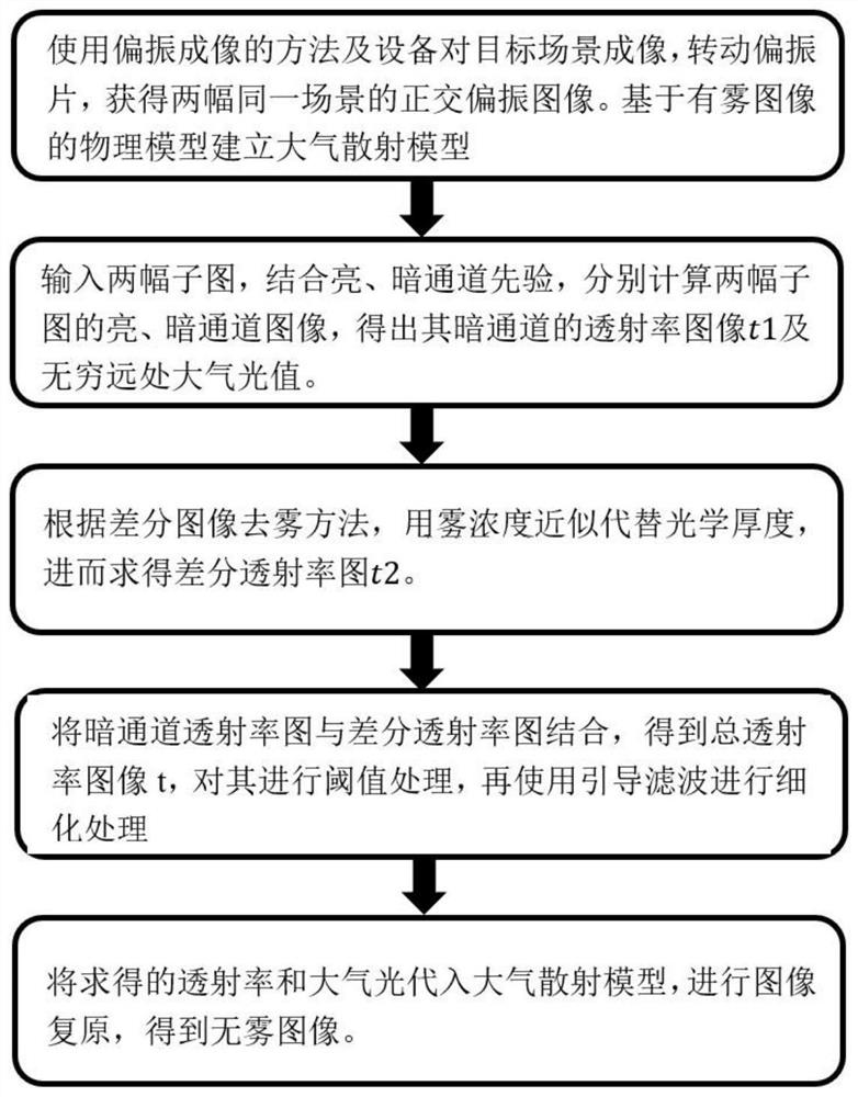
[0043] A polarization image defogging method based on differential polarization combined with prior acquisition of bright and dark channels to obtain transmittance, specifically comprising the following steps:

[0044] (1) Use the method and equipment of polarized imaging to image the target scene, rotate the polarizer, and obtain two orthogonally polarized images of the same scene; respectively, the light intensity map (denoted as I) that fog has the least influence on the image / / ) and the light intensity map that has the greatest influence on the image (denoted as I ⊥ ); read two orthogonal images in MATLAB (the following steps are all implemented on the MATLAB platform).

[0045] According to the imaging characteristics of the scattering environment, the atmospheric scattering model includes two parts:

[0046] Scene target direct light transmission: D(x, y) = L(x, y)t(x, y)

[0047] Atmospheric light: B(x,y)=A ∞ [1-t(x,y)]

[0048] Where (x, y) represents the coordin...


PUM


Abstract

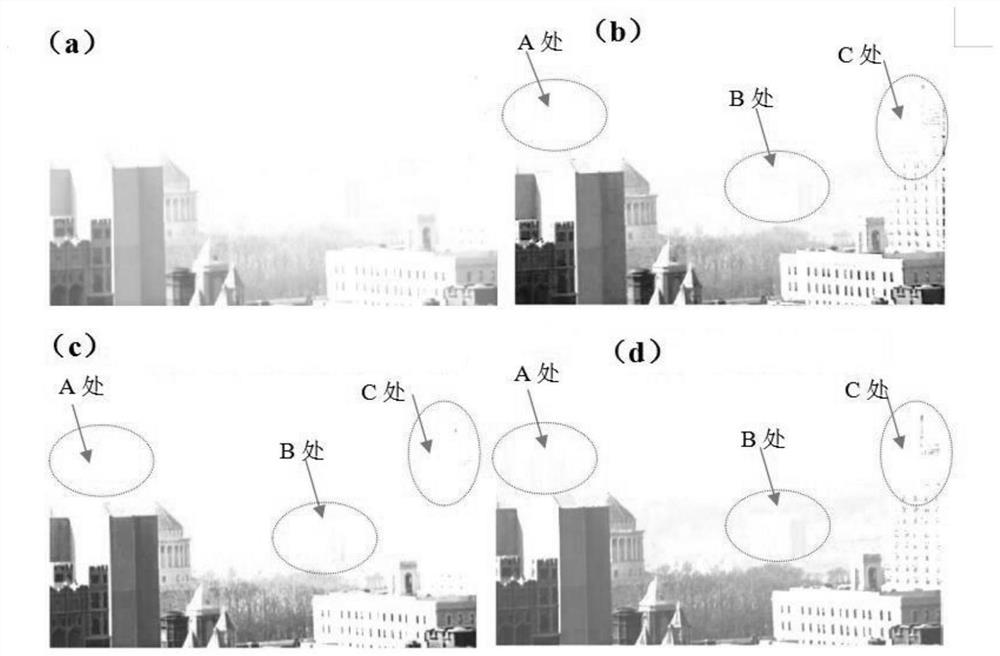
The invention discloses a polarized image defogging method for obtaining transmissivity based on differential polarization, and belongs to the technical field of image defogging processing. The method comprises the following steps of acquiring two orthogonal polarization images of the same scene by using a polarization imaging method, establishing an atmospheric scattering model based on the foggy image physical model, and respectively calculating bright and dark channel images of the two sub-images in combination with bright and dark channel priori to obtain a transmissivity image t1 of the dark channel and an atmosphere light value at infinity, according to a difference image defogging method, approximately replacing the optical thickness by fog concentration to acquire a difference transmittance graph t2; and combining the dark channel transmissivity image with the differential transmissivity image to obtain a total transmissivity image, carrying out threshold processing on the total transmissivity image, and then carrying out refinement processing by using guide filtering; and substituting the obtained transmissivity and the atmospheric light into an atmospheric scattering model to obtain a fogless image. Image quality is obviously improved, more object reflected light information is obtained, and the definition of the restored image is improved.

Description

technical field [0001] The invention relates to a polarization image defogging method based on differential polarization to obtain transmittance, and belongs to the technical field of image defogging processing. Background technique [0002] In recent years, fog and haze weather has become more and more serious, which leads to the degradation of the image quality acquired by the imaging system, which seriously affects the analysis and judgment of the visual system; therefore, improving the clarity of foggy images to obtain better visual effects and richer visual effects Algorithms for detail information processing have become the focus of current research. At present, many researchers have proposed many methods for processing foggy images; since the atmospheric light formed by scattering particles such as haze and sunlight has partial polarization characteristics, polarization optical imaging dehazing is suitable for various scenarios. All kinds of haze weather has a wide r...

Claims


Application Information

Patent Timeline
IPC IPC(8): G06T5/00G06T5/50
CPCG06T5/50G06T2207/10004G06T5/73Y02A90/10
Inventor 宋雪艳宫爱玲李尚位
Owner KUNMING UNIV OF SCI & TECH
Learn More