
Interval heat dissipation type electrical cabinet

An electric cabinet and heat dissipation technology, which is applied in the field of spaced heat dissipation electric cabinets, can solve the problems of entering the interior of the electric cabinet, damage to internal electrical components, and low flexibility of use, so as to improve heat absorption efficiency, reliability, and heat dissipation efficiency effect

Pending Publication Date: 2021-05-25
ANHUI TIANYING ELECTRIC TRANSMISSION
View PDF12 Cites 2 Cited by
  • Summary
  • Abstract
  • Description
  • Claims
  • Application Information

AI Technical Summary

Problems solved by technology

[0003] The applicant found that the current electrical cabinets often use internal and external air exchange to take away the heat generated by the internal electrical components for heat dissipation, and the direct circulation of internal and external air may easily cause external water vapor and dust to enter the interior of the electrical cabinet, which may easily lead to internal electrical components. Damage, and the heat dissipation mechanism inside the electrical cabinet is often a fixed structure, the overall heat dissipation efficiency is certain, it is difficult to flexibly adjust the specific heat dissipation structure according to the specific installation quantity and position of the specific electrical components and the required heat dissipation power, and the use flexibility is low

Method used


Image

  • Interval heat dissipation type electrical cabinet
  • Interval heat dissipation type electrical cabinet
  • Interval heat dissipation type electrical cabinet

Examples


Embodiment Construction

[0034] In order to make the purpose, technical solutions and advantages of the present disclosure clearer, the present disclosure will be further described in detail below in conjunction with specific embodiments.

[0035] It should be noted that, unless otherwise defined, the technical terms or scientific terms used in one or more embodiments of the present specification shall have ordinary meanings understood by those skilled in the art to which the present disclosure belongs. "First", "second" and similar words used in one or more embodiments of the present specification do not indicate any order, quantity or importance, but are only used to distinguish different components. "Comprising" or "comprising" and similar words mean that the elements or items appearing before the word include the elements or items listed after the word and their equivalents, without excluding other elements or items. Words such as "connected" or "connected" are not limited to physical or mechanica...


PUM


Abstract

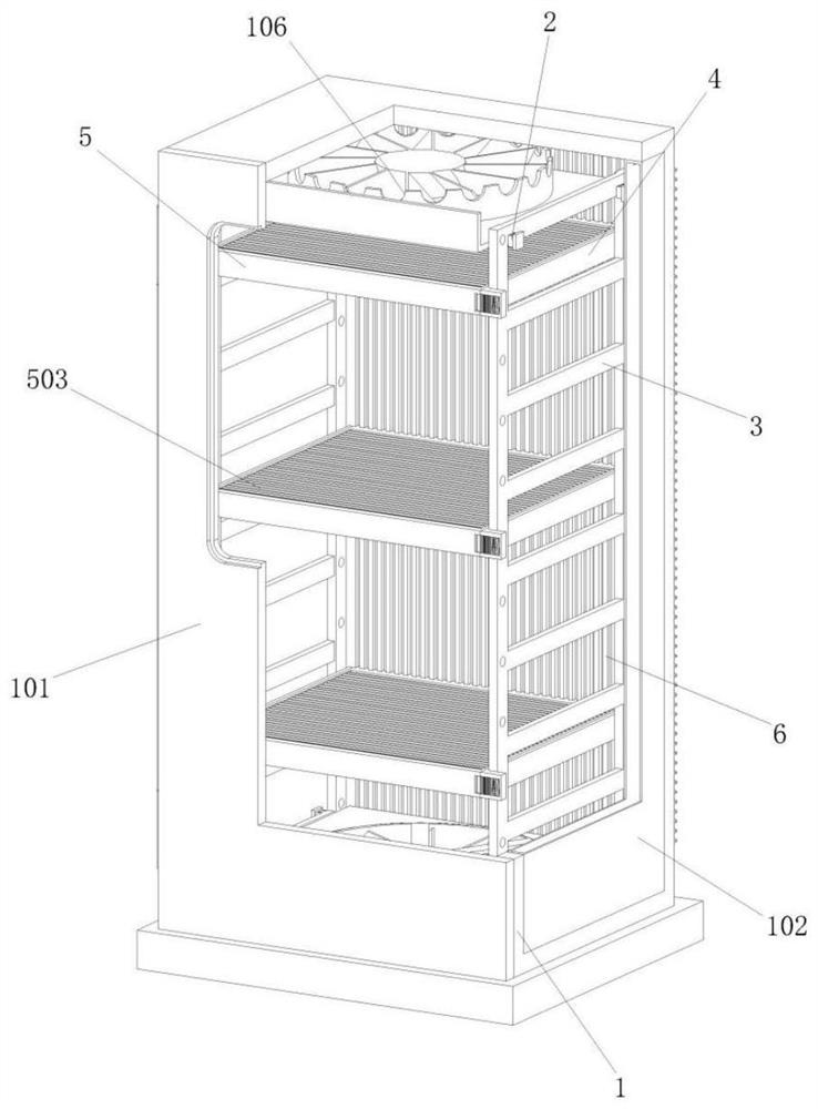
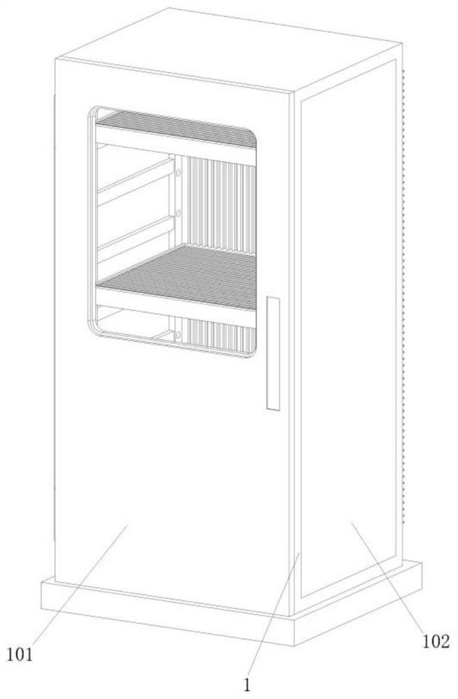
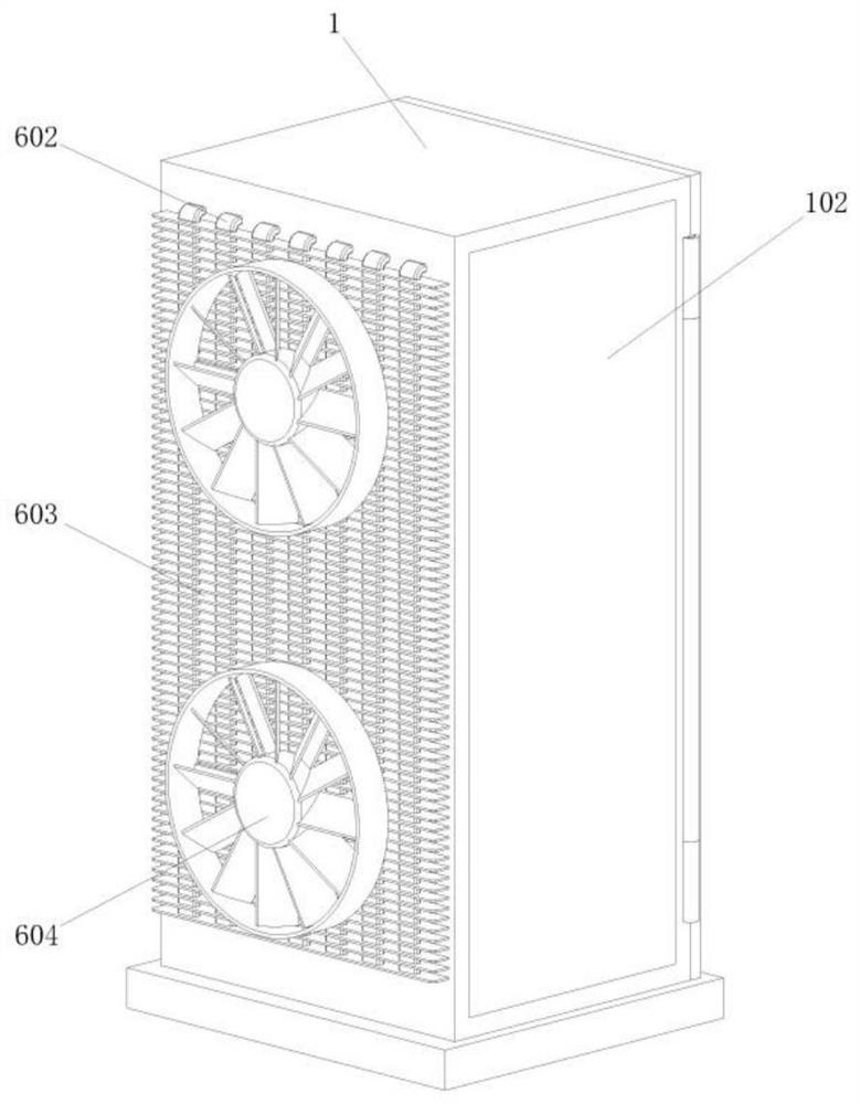
One or more embodiments of the invention provide an interval heat dissipation type electrical cabinet, which comprises a cabinet body, a cabinet door is arranged on the front surface of the cabinet body, side baffles are arranged on the left side and the right side of the cabinet body, a hollow interlayer is arranged in the middle of each side baffle, an upper side opening is formed in the upper part of the inner side of each side baffle, a lower side opening is formed in the lower part of the inner side of the side baffle plate; and a suspension mounting frame, which is arranged on the inner side face of the side baffle, and a rubber connecting block is arranged on the outer side of the suspension mounting frame. Corresponding electrical devices can be installed through the device installation frame arranged in the cabinet body, the electrical cabinet is provided with a plurality of unit heat dissipation frames, and each unit heat dissipation frame can be rapidly installed on the device installation frame and is attached to the vertical heat conduction plate, so that the overall heat absorption efficiency of the vertical heat conduction plate is improved. And meanwhile, the positions and the number of the unit heat dissipation frames can be conveniently adjusted according to the installation requirements of internal devices, and the electrical cabinet is more convenient and flexible to use.

Description

technical field [0001] One or more embodiments of this specification relate to the technical field of electric cabinets, and in particular, to a partitioned heat dissipation electric cabinet. Background technique [0002] The electrical cabinet is made of steel to protect the normal operation of the components. The materials for the electrical cabinet are generally divided into two types: hot-rolled steel plate and cold-rolled steel plate. Compared with hot-rolled steel plate, cold-rolled steel plate is softer and more suitable for electrical appliances. The production of cabinets, electrical cabinets are widely used mainly in chemical industry, environmental protection industry, power system, metallurgical system, industry, nuclear power industry, fire safety monitoring, transportation industry and so on. [0003] The applicant found that the current electrical cabinets often use internal and external air exchange to take away the heat generated by the internal electrical c...

Claims


Application Information

Patent Timeline
IPC IPC(8): H05K7/14H05K7/20
CPCH05K7/14H05K7/2039H05K7/20418H05K7/20172Y02D10/00
Inventor 马琳戴翔
Owner ANHUI TIANYING ELECTRIC TRANSMISSION
Features
  • Generate Ideas
  • Intellectual Property
  • Life Sciences
  • Materials
  • Tech Scout
  • Unparalleled Data Quality
  • Higher Quality Content
  • 60% Fewer Hallucinations
Learn More