Automatic cleaning mopping vehicle with multiple rows of mopping cloth

A technology for automatic cleaning and mopping vehicles, applied in the direction of cleaning carpets, cleaning floors, automatic detection of obstacles, etc., to achieve the effect of reducing the space of the vehicle body, expanding the scope of use, and making turns and U-turns convenient

Pending Publication Date: 2021-05-28
SUINING CHANGFENG MECHANICAL TECH
View PDF2 Cites 1 Cited by
  • Summary
  • Abstract
  • Description
  • Claims
  • Application Information

AI Technical Summary

Problems solved by technology

[0003] The purpose of the present invention is to overcome the shortcomings of the existing reel-type floor mopping vehicles, and proposes a technical solution in which no chute is provided on both sides of the runner, and the substrate is directly surrounded on the runner from the outside of the runner circle, that is, a multi-row mopping handkerchief. Automatic cleaning mopping vehicle, hereinafter referred to as mopping vehicle

Method used


Image

  • Automatic cleaning mopping vehicle with multiple rows of mopping cloth
  • Automatic cleaning mopping vehicle with multiple rows of mopping cloth
  • Automatic cleaning mopping vehicle with multiple rows of mopping cloth

Examples


Embodiment Construction

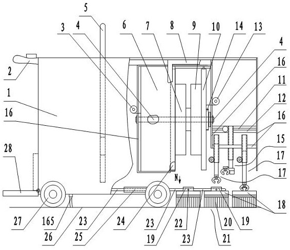
[0024] figure 1 In the middle is the overall structure diagram of the hand-push mopping vehicle. The mopping car includes a variable cleaning pool, a frame device, a wrapping mechanism, a runner, a turning clip device, a side clip device, a guide clip device, a car body, and a mop. Above the front wheels 27 in the vehicle body 1 is the variable washing tank 6 . The variable cleaning tank 6 is hereinafter referred to as the cleaning tank 6 . The cleaning tank is in the shape of a cylindrical shell, and the circular shell is oriented left and right. In the figure, the right side of the cleaning pool is a runner, which consists of a left runner 7 and a right runner 9. The left and right runners are connected in the middle. There is a slot in the middle of the runner. A main shaft 4 passes through the center of the cleaning tank and the center of the runner. Both ends of the main shaft 4 are fixed on the racks 16 on the left and right sides of the cleaning tank. The left ca...


PUM


Abstract

An automatic cleaning mopping vehicle with multiple rows of mopping cloth comprises a variable cleaning pool, a shell frame device, a winding mechanism, a rotating wheel, a rotating clamping device, a side clamping device, a guide clamping device, a vehicle body and the mopping cloth. A mopping strip is connected to a thin base plate through canvas. When mopping the floor and transferring the mopping cloth, the upper surface of the mopping cloth is connected with the shell frame. When the mopping cloth are cleaned, the rotating clamping device transfers the first row of mopping cloth in front of the vehicle to the position below the rotating wheel, a hanging clamping device of the winding mechanism hangs the two ends of the mopping cloth base plate, the base plate is wound on the outer circle of the rotating wheel moving out of the cleaning pool, and the two ends of the base plate are automatically fixed. And the lower guide clamping device clamps the third row of mopping cloth and the second row of mopping cloth on the rear side to be sequentially pushed forwards for replacement. And the cleaned mopping cloth are transferred to the third row of mopping cloth to mopping cloth the floor. An operator can quickly take down the cleaned mopping cloth from the mopping vehicle through the handle rod to mopping cloth the floor in narrow areas with many obstacles. The three rows of mopping cloth are used for cleaning and mopping the floor in turn, so that the floor is cleaner, the working efficiency is higher, and the use is more convenient. The mopping vehicle can be a hand-push type vehicle, a driving type vehicle and an unmanned type vehicle.

Description

technical field [0001] The invention belongs to the field of environmental protection machinery, in particular to an automatic cleaning and mopping vehicle for multi-row mops. Background technique [0002] Now it is very common for long strip mop to be used in office area, community, school, hospital and family. However, the cleaning and dehydration of the long mop is very inconvenient. There are mopping machines with automatic cleaning and dehydration, such as: reel type automatic cleaning and mopping machine, patent number: ZL201810710326.1; reel cleaning type continuous mopping machine, patent number: ZL 201821033792.2, etc. The technical solution adopted is to mop The substrate connected with the mopping strips under the handkerchief is inserted into the shell plate with the chute on both sides, the cleaning pool is provided with a runner, and the outer circle of the runner is provided with chute on both sides. When cleaning, align the chutes on both sides of the mop s...

Claims


Application Information

Patent Timeline
Patent Type & Authority Applications(China)
IPC IPC(8): A47L11/293A47L11/40
CPCA47L11/293A47L11/40A47L11/4011A47L11/4038A47L11/4061A47L2201/00A47L2201/04
Inventor 邹家福邹永平邹家鸿
Owner SUINING CHANGFENG MECHANICAL TECH
Why Eureka
Try Eureka