Metal composite material forging device

A metal composite material and symmetrical technology, applied in forging/pressing/hammer devices, metal processing equipment, manufacturing tools, etc., can solve problems affecting the precision of forgings, knocking deflection, falling, etc., to achieve simple operation and use convenient effect

Inactive Publication Date: 2021-05-28
郁家府
View PDF0 Cites 6 Cited by
  • Summary
  • Abstract
  • Description
  • Claims
  • Application Information

AI Technical Summary

Problems solved by technology

[0004] The purpose of the present invention is to solve the problem that when the existing forging hammer strikes forgings, the placement of the forgings is not stable enough, which leads to the deflection of the percussion, and the rust ash attached to the forgings falls off during the percussion forging. Falling to the bottom of the forging, it is easy to affect the accuracy of the forging when the forging is forged, and a metal composite forging device is proposed

Method used


Image

  • Metal composite material forging device
  • Metal composite material forging device
  • Metal composite material forging device

Examples


Embodiment 1

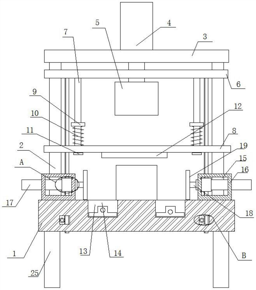
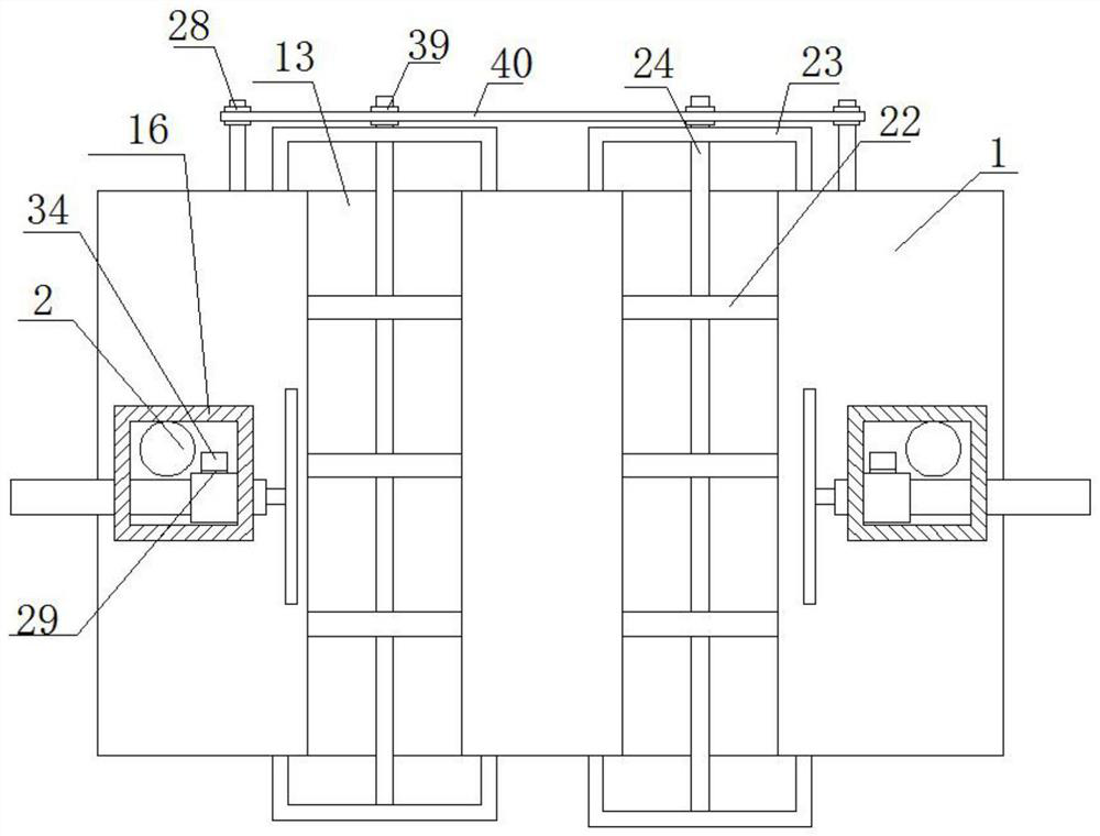
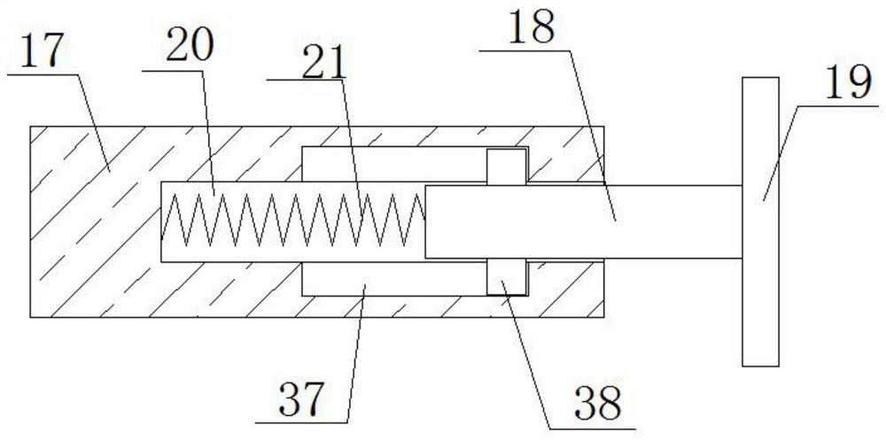
[0029] refer to Figure 1-5 , a metal composite forging device, comprising a base 1, the top of the base 1 is rotatably connected to two symmetrically arranged support rods 2, the top ends of the two support rods 2 are rotatably connected to the same top plate 3, and the top of the top plate 3 is fixedly installed There is a cylinder 4, a forging hammer 5 is fixedly installed on the piston of the cylinder 4, a push plate 6 and a moving plate 8 are movably connected to the two support rods 2, and the push plate 6 is fixedly connected with the piston of the cylinder 4, the bottom of the push plate 6 Two symmetrically arranged push rods 7 are fixedly installed, and the push rod 7 is slidingly connected with the moving plate 8. The bottom of the moving plate 8 is fixedly installed with a backing plate 12, and the supporting rod 2 is rotatably connected with a positioning box 16, which slides on the positioning box 16. A moving rod 17 is connected, and the ends of the two moving ro...

Embodiment 2

[0040] refer to Figure 1-5 , a metal composite forging device, comprising a base 1, the top of the base 1 is rotatably connected to two symmetrically arranged support rods 2, the top ends of the two support rods 2 are rotatably connected to the same top plate 3, and the top of the top plate 3 is connected by bolts A cylinder 4 is fixed, and a forging hammer 5 is welded on the piston of the cylinder 4. A push plate 6 and a moving plate 8 are movably connected to the two support rods 2, and the push plate 6 is fixedly connected to the piston of the cylinder 4. The bottom of the push plate 6 Two symmetrically arranged push rods 7 are welded, the push rod 7 is slidably connected with the moving plate 8, the bottom of the moving plate 8 is welded with a backing plate 12, the supporting rod 2 is rotatably connected with a positioning box 16, and the positioning box 16 is slidably connected with a Moving rod 17, one end of the two moving rods 17 close to each other is slidably conne...


PUM


Abstract

The invention belongs to the technical field of material forging equipment, particularly relates to a metal composite material forging device. The metal composite material forging device aims to solve the problems that when a forge piece is knocked and forged by an existing forging hammer, because the forge piece is not stably placed, knocking deflection is caused, and rust ash attached to the outside of the forge piece falls below the forge piece during knocking forging, so the forging precision of the forge piece is easily affected. According to the technical scheme, the forging device comprises a base, the top of the base is rotationally connected with two symmetrically-arranged supporting rods, the top ends of the two supporting rods are rotationally connected with a same top plate, an air cylinder is fixedly installed on the top of the top plate, a forging hammer is fixedly installed on a piston of the air cylinder, a push plate and a movable plate are movably connected to the two supporting rods, and the push plate is fixedly connected with the piston of the air cylinder. The device is easy to operate and convenient to use, a forge piece can be stably clamped and forged, meanwhile, rust ash on the forge piece can be collected and scraped out, and people can use the device conveniently.

Description

technical field [0001] The invention relates to the technical field of metal material forging equipment, in particular to a metal composite material forging device. Background technique [0002] Metal composite materials refer to composite materials formed by metallurgical bonding at the interface using composite technology or various metals with different chemical and mechanical properties, which greatly improve the thermal expansion, strength, fracture toughness and impact toughness of a single metal material , wear resistance, electrical properties, magnetic properties and many other properties, so it is widely used in products widely used in petroleum, chemical industry, shipbuilding, metallurgy, mining, machinery manufacturing, electric power, water conservancy, transportation, environmental protection, pressure vessel manufacturing, food , brewing, pharmaceutical and other industrial fields. With the continuous development and progress of society, the use of metal com...

Claims


Application Information

Patent Timeline
Patent Type & Authority Applications(China)
IPC IPC(8): B21J13/02B21J13/10B21J13/08
CPCB21J13/02B21J13/085B21J13/10
Inventor 郁家府
Owner 郁家府
Why Eureka
Try Eureka