Hot punching device for runner of MIM (Metal Injection Molding) part

A technology of injection molded parts and hot punching, which is applied in the field of MIM injection molded parts flow channel hot punching device, which can solve the problems affecting the appearance and function of injection molded parts, the melting of injection molded parts body, and the crack of injection molded parts body, so as to improve the quality and process in one step In place, the effect of smooth incision

Active Publication Date: 2021-05-28
杭州铭赫科技有限公司
View PDF7 Cites 1 Cited by
  • Summary
  • Abstract
  • Description
  • Claims
  • Application Information

AI Technical Summary

Problems solved by technology

Moreover, different raw materials have different heat conduction effects. If the punching speed is too fast, the heat conduction will not be enough to make the cut part reach a semi-melted state, resulting in a rough cut part; Too much heat conducts to the incision part, which makes the body part of the injection molded part melt and affects the appearance and function of the injection molded part. Therefore, the traditional heating tool punching method is not suitable for all injection molded parts
[0004] In the traditional punching process of injection molded parts, the injection molded part is fixed, and then the runner part is quickly punched with a knife. However, due to the low hardness of the injection molded part, the cut part is subjected to excessive punching force from the side of the knife during punching. Large, the punching force will be transmitted to the main body of the injection molded part, and it is very easy to cause deformation of the cut or cracks on the main body of the injection molded part

Method used


Image

  • Hot punching device for runner of MIM (Metal Injection Molding) part
  • Hot punching device for runner of MIM (Metal Injection Molding) part
  • Hot punching device for runner of MIM (Metal Injection Molding) part

Examples


Embodiment Construction

[0024] The present invention will be described in further detail below in conjunction with the accompanying drawings.

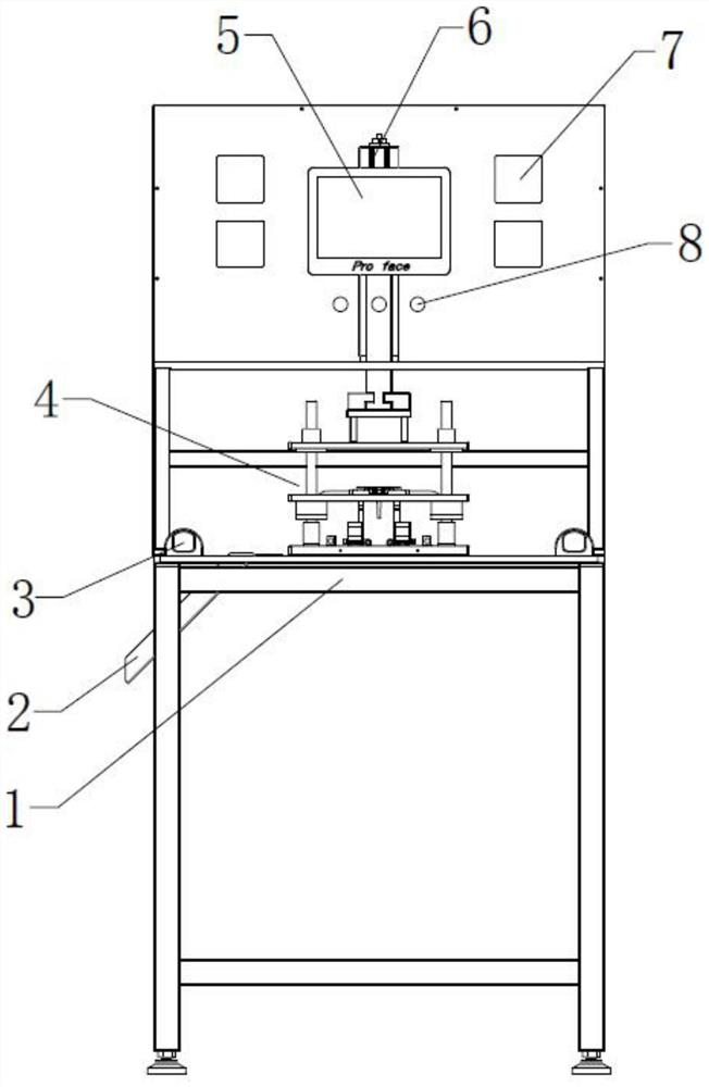
[0025] Such as figure 1 A punching device suitable for small MIM injection molded parts is shown, including a device table 1, an operating part of the device and a main structure 4 of the device. The device table is a desktop frame, the main structure is installed on the device table, and the electric control part of the device is installed above the main structure, including human-computer interaction parts such as touch screen 5, operation button 8 and temperature control table, The touch screen can set the parameters of the action of the mechanical arm 6, and the temperature control table 7 can control the temperature of each cutter. Two touch switches 3 are arranged on the device table, and a hole is provided and a slideway 2 is installed through the hole, which is used for throwing and placing the excised runner, and a barrel is arranged at the end of t...


PUM


Abstract

The invention relates to a hot punching device for a runner of an MIM (Metal Injection Molding) part. The hot punching device for the runner of the MIM part comprises a device table and is characterized in that a main body structure and an electric control system are arranged on the device table, wherein the main body structure comprises a bottom layer plate; the bottom layer plate is provided with a cutter used for punching a pouring gate of the injection molding part; a cutter body is internally provided with at least one heating rod and one thermocouple and is connected with a temperature control meter of the electric control system; guide columns and elastic reset mechanisms are arranged at the four corners of the bottom layer plate so as to be connected with a middle layer plate; a jig used for positioning the injection molding part is arranged on the middle layer plate; an upper layer pressing block capable of being controlled by a lifting mechanism to ascend and descend is arranged on the upper part of the middle layer plate, and is pressed downwards to make contact with the injection molding part; and the middle layer plate is pushed to overcome the elastic force of an elastic reset mechanism and move downwards until the injection molding part is in contact with the cutting edge of the cutter to cut off the runner. According to the hot punching device for the runner of the MIM part provided by the invention, the quality of a notch of the injection molding part is improved, and the yield of product production is improved.

Description

technical field [0001] The invention relates to the field of MIM powder metallurgy injection molding, in particular to a hot punching device for flow channels of MIM injection molded parts. Background technique [0002] Nowadays, many products are made by MIM process, and the first process of MIM process is injection molding. The general MIM parts will be taken out of the mold together with the injection runner after the injection molding is completed, and the runner and the injection molded part need to be separated in a subsequent process. At present, the methods of separating the runner and the injection molded part are mainly separated by hand and punched with a knife. However, no matter whether it is done manually or with a knife, some debris will remain at the gate of the injection molded part after separation, and the surface of the incision is very rough. Rough, and it's hard to control the position when detached. It is necessary to add a process to re-adjust the p...

Claims


Application Information

Patent Timeline
Patent Type & Authority Applications(China)
IPC IPC(8): B22F3/22B22F3/24
CPCB22F3/225B22F3/24B22F2003/247
Inventor 朱益浩
Owner 杭州铭赫科技有限公司
Why Eureka
Try Eureka