Shaft surface repairing system and method for additive composite micro-rolling

A technology of surface repair and additive printing, applied in the direction of additive processing, additive manufacturing, etc., can solve the problems of restricting the reuse of shaft parts, poor wear resistance, and limited coating thickness, so as to reduce the formation of tensile stress and improve the overall Effect of performance improvement and reduction of cracking tendency

Active Publication Date: 2021-05-28
CRRC IND INST CO LTD +1
View PDF7 Cites 8 Cited by
  • Summary
  • Abstract
  • Description
  • Claims
  • Application Information

AI Technical Summary

Problems solved by technology

[0003] At present, domestic methods for repairing worn shafts mainly include arc surfacing, laser cladding, thermal spraying, and electroplating. Although the bonding strength of the repair layer by the spraying method is high, the deformation is large, and it is not suitable for large-scale repairs; the arc surfacing method and the laser cladding method are essentially equivalent to the accumulation of welding on the surface of the substrate with high temperature, and relatively The technological process is relatively simple, so the arc surfacing method and laser cladding method are the most widely used in automatic repair.
[0004] However, during the implementation of the arc surfacing method and the laser cladding method, it is inevitable to have a corresponding thermal impact on the matrix of the shaft parts, and the structural changes and strength degradation in the heat-affected zone will directly affect the service of the shaft parts. Life and safety; In addition, the metallurgical quality of the surfacing layer or laser cladding layer is difficult to control, and it is easy to produce metallurgical defects such as pores and lack of fusion. These two factors make the overall performance of the repaired shaft unable to meet the requirements for re-putting into use. This severely restricts the reuse of shaft parts after repair

Method used


Image

  • Shaft surface repairing system and method for additive composite micro-rolling
  • Shaft surface repairing system and method for additive composite micro-rolling
  • Shaft surface repairing system and method for additive composite micro-rolling

Examples


Embodiment Construction

[0051] In order to make the purpose, technical solutions and advantages of the present invention clearer, the technical solutions in the present invention will be clearly and completely described below in conjunction with the accompanying drawings in the present invention. Obviously, the described embodiments are part of the embodiments of the present invention , but not all examples. Based on the embodiments of the present invention, all other embodiments obtained by persons of ordinary skill in the art without creative efforts fall within the protection scope of the present invention.

[0052] In the description of the embodiments of the present invention, it should be noted that the terms "center", "longitudinal", "transverse", "upper", "lower", "front", "rear", "left", "right" , "vertical", "horizontal", "top", "bottom", "inner", "outer" and other indicated orientations or positional relationships are based on the orientations or positional relationships shown in the drawi...


PUM


Abstract

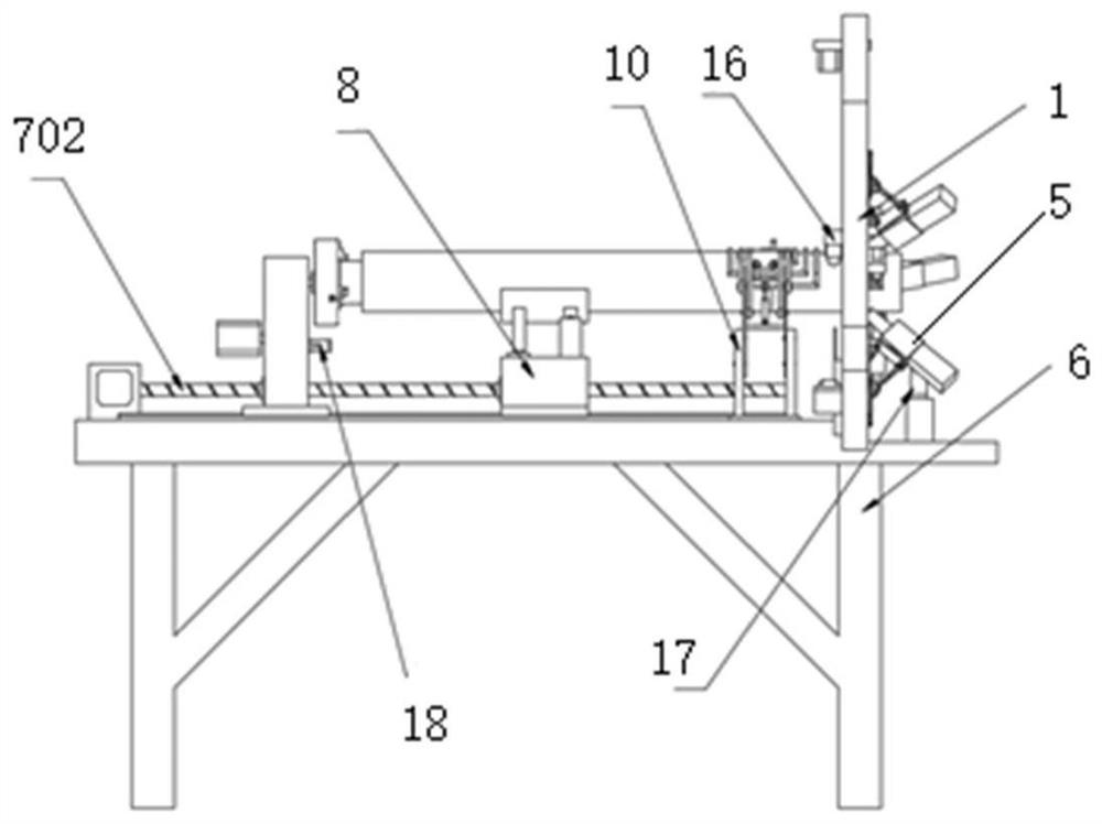
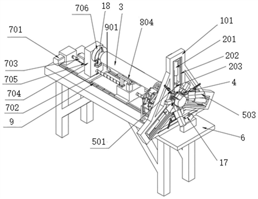
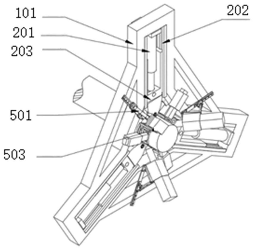
The invention relates to the technical field of additive shaft repairing, and provides a shaft surface repairing system and method for additive composite micro-rolling. The system comprises a frame, a plurality of groups of spinning units evenly distributed in the circumferential direction are arranged on the frame, and a middle wear shaft repairing area is constructed; each of the spinning units comprises a first driving device, a first guide rail, a first sliding block and a roller, wherein the first driving device and the first guide rail are fixed to the frame, an output end of the first driving device is connected with the first sliding block, the first sliding block is movably arranged on the first guide rail, the roller is connected with the first sliding block, and the roller surface of the roller is opposite to the circumferential surface of a wear shaft in the middle wear shaft repairing area; and a heating mechanism and an additive printing mechanism are arranged on the frame. According to the shaft surface repairing system for the additive composite micro-rolling provided by the invention, additive shaft repairing and micro-rolling of a repaired part are synchronously achieved, the microstructure and the mechanical property of the repaired shaft are comprehensively improved, the overall performance of the repaired shaft is improved, and the repaired shaft can be put into use again.

Description

technical field [0001] The invention relates to the technical field of additive shaft repair, in particular to a shaft surface repair system and method for additive composite micro-rolling. Background technique [0002] In large machines, shaft parts are an essential part, and during long-term use, there will inevitably be some surface wear or scratches, which will affect the normal use of the machine. Most of the shaft parts are expensive, so it is of great significance to repair the surface of the failed shaft parts. On the one hand, it reduces the cost of repairing the machine for the enterprise. On the other hand, by repairing the shaft instead of remanufacturing a new shaft, it greatly Improved resource utilization and cost savings. [0003] At present, domestic methods for repairing worn shafts mainly include arc surfacing, laser cladding, thermal spraying, and electroplating. Although the bonding strength of the repair layer by the spraying method is high, the defor...

Claims


Application Information

Patent Timeline
Patent Type & Authority Applications(China)
IPC IPC(8): B22F7/08B22F10/66B22F12/17B33Y30/00B33Y40/20
CPCB22F7/062B22F3/18B22F3/24B33Y30/00B33Y40/20B22F2007/068Y02P10/25
Inventor 祝弘滨张琦张家昊刘昱折洁王行涛龚明
Owner CRRC IND INST CO LTD
Why Eureka
Try Eureka