Device and method for removing plating layer on inner wall of porous structure of filter

A hole-shaped structure and filter technology, which is applied in the field of removal device for the inner wall of the filter hole-shaped structure, can solve the problems of low processing efficiency, unguaranteed stability, and increased cost, and achieve the effect of improving work efficiency

Active Publication Date: 2021-05-28
WUHAN HGLASER ENG CO LTD
View PDF12 Cites 0 Cited by
  • Summary
  • Abstract
  • Description
  • Claims
  • Application Information

AI Technical Summary

Problems solved by technology

However, since the laser emission direction is vertically downward and unchangeable, this equipment can only remove the metal material on the top surface. If it is necessary to remove the metal material on the inner wall of the hole-like structure on the side wall, it can only be removed by multiple translations and rotations. Axis movement module, so that the side wall is exposed to the top surface to be further removed by laser, which will also lead to low processing efficiency of the equipment, stability cannot be guaranteed, and the four-axis movement module is bulky and impractical, and will increase additional costs

Method used


Image

  • Device and method for removing plating layer on inner wall of porous structure of filter
  • Device and method for removing plating layer on inner wall of porous structure of filter

Examples


Embodiment 1

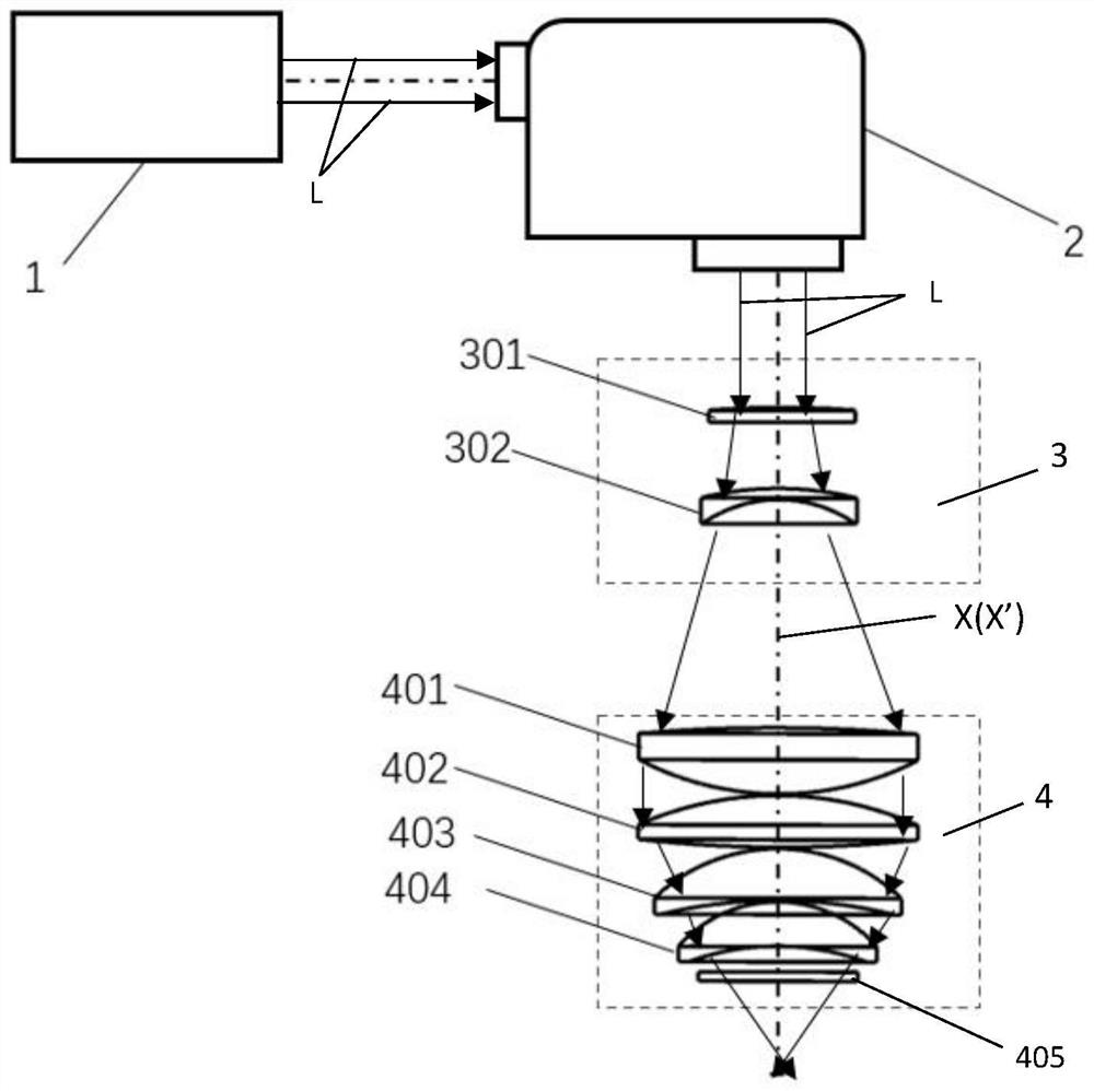
[0030] Such as Figure 1-2 As shown, the present embodiment provides a device for removing the coating on the inner wall of the filter hole structure, which includes:

[0031] a laser 1, which is used to generate and output a laser beam L;

[0032] A vibrating mirror 2, which is used to deflect the laser beam L output by the laser 1, so as to adapt to the coating removal requirements of different formats;

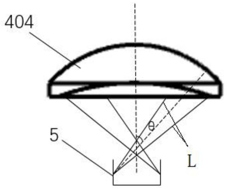
[0033] Lens group 3 and focusing lens group 4, the laser beam L emitted from the galvanometer 2 enters the focusing lens group 4 after changing the angle through the lens group 3, and the focusing lens group 4 processes the laser beam L so that the laser beam L from the focusing lens group The laser beam L emitted in 4 has an inclination angle θ, and acts on the inner wall of the filter hole structure 5 to realize the removal of the coating on the inner wall of the filter hole structure. In this embodiment, the inclination angle θ satisfies the condition: 30°≤θ≤60 ° (pref...

Embodiment 2

[0037] The only difference between this embodiment and Embodiment 1 is that the device for removing the coating on the inner wall of the filter hole structure also includes:

[0038] The first movement module, which is connected to the vibrating mirror 2, is used to drive the vibrating mirror 2 to move along the optical axis X' of the laser beam L output from the vibrating mirror 2, so as to adjust the distance between the vibrating mirror 2 and the lens group 3. The distance can further adjust the aperture size of the spot to meet the removal requirements of different coatings.

Embodiment 3

[0040] The only difference between this embodiment and Embodiment 1 or 2 is that the lens group 3 includes:

[0041] The plano-convex lens 301 located at the incident end and the plano-convex lens 302 located at the exit end, and the optical axes of the plano-convex lens 301 and the plano-concave lens 302 coincide, the exit angle of the laser beam changes after the comprehensive action of the plano-convex lens 301 and the plano-concave lens 302, such as the exit angle become bigger;

[0042] Meanwhile, the focusing lens group 4 includes:

[0043] The first biconvex lens 401, the first biconvex lens 402, the first meniscus lens 403, the second meniscus lens 404 and the protective lens 405 arranged in sequence along the direction from the incident end to the exit end, through the plano-concave lens 302 of the lens group 3 After the laser beam passes through the comprehensive action of the first lenticular lens 401, the first lenticular lens 402, the first meniscus lens 403, the...


PUM


Abstract

The invention relates to a device and method for removing a plating layer on the inner wall of a porous structure of a filter. The device comprises a laser device used for generating and outputting laser beams, a galvanometer used for deflecting the laser beams output by the laser device, a lens set and a focusing lens set. The laser beams emitted from the galvanometer enter the focusing lens set after the angles of the laser beams are changed through the lens set, the focusing lens set processes the laser beams, so that the laser beams emitted from the focusing lens set have inclination angles theta and act on the inner wall of the porous structure of the filter, and the plating layer on the inner wall of the porous structure of the filter is removed. According to the device and method, lasers are deflected and directly act on the inner wall of the porous structure of the filter, so that the plating layer on the inner wall of the porous structure is removed, and therefore the removal efficiency is improved.

Description

technical field [0001] The invention relates to the field of optoelectronic component manufacturing, in particular to a device and method for removing coatings on the inner wall of a filter hole structure. Background technique [0002] The filter is the core component of the radio frequency of the base station. Its main function is to pass the signal of a specific frequency and greatly attenuate the signal of other frequencies. There are three main types of filters at present: metal coaxial cavity, ceramic dielectric resonator and ceramic dielectric. Among them, with the development and deepening of 5G technology, ceramic dielectrics have gradually become the mainstream due to their advantages such as small size, high Q value, low insertion loss, good stability, and high power withstand. [0003] However, since the ceramic itself is not conductive, it needs to be metallized to make it have the function of a filter, mainly including methods such as spraying silver, immersion...

Claims


Application Information

Patent Timeline
Patent Type & Authority Applications(China)
IPC IPC(8): B23K26/36B23K26/082B23K26/064
CPCB23K26/36B23K26/082B23K26/064B23K26/0648
Inventor 王雪辉戚云飞温彬喻浩王建刚
Owner WUHAN HGLASER ENG CO LTD
Why Eureka
Try Eureka