Feeding and discharging pushing mechanism of laser marking device

A technology of laser marking and pushing mechanism, applied in the field of laser marking machines, can solve the problems of untimely retraction and extension of lifting blocks, damage to parts and equipment, low feeding efficiency, etc., so as to reduce waiting time and achieve accurate position. , smooth sliding effect

Active Publication Date: 2021-05-28
NINGBO BEILONG PRECISION MOLDING
View PDF7 Cites 0 Cited by
  • Summary
  • Abstract
  • Description
  • Claims
  • Application Information

AI Technical Summary

Problems solved by technology

[0004] In order to overcome the problem that the loading and unloading of the laser marking machine in the prior art is generally carried out manually, there are problems of low feeding efficiency and high labor cost, and provides A laser marking device loading and unloading push mechanism, which can realize automatic loading and unloading and conveying functions, and can solve the problem of damage to parts and equipment caused by the untimely retraction and extension of the lifting block when the control timing of the push mechanism is chaotic

Method used


Image

  • Feeding and discharging pushing mechanism of laser marking device
  • Feeding and discharging pushing mechanism of laser marking device
  • Feeding and discharging pushing mechanism of laser marking device

Examples


Embodiment 1

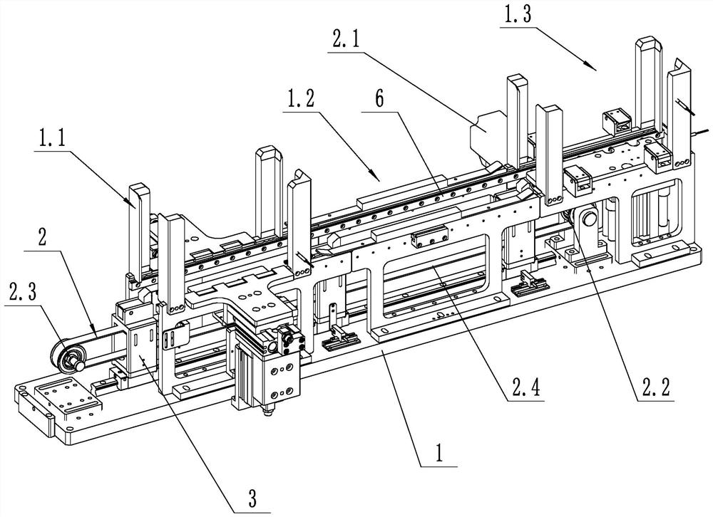
[0030] Such as figure 1 As shown, a laser marking device loading and unloading push mechanism includes a support frame 1, a push drive mechanism 2, a push assembly 3 and a tray, the tray is arranged on the support frame 1 and is slidably connected with the support frame 1, and the push drive mechanism 2 is fixed On the support frame 1, the support frame 1 includes a loading station 1.1, a processing station 1.2 and a blanking station 1.3, and the push assembly 3 can span the loading station 1.1, processing station under the action of the driving mechanism 2. Station 1.2 and unloading station 1.3, push the tray with products from loading station 1.1 to processing station 1.2, and then push the processed tray from processing station 1.2 to unloading station 1.3. There are two pushing assemblies 3, and the two pushing assemblies 3 are arranged at intervals of one station. The two push assemblies 3 are connected with the same push drive mechanism 2 . The driving mechanism 2 incl...

Embodiment 2

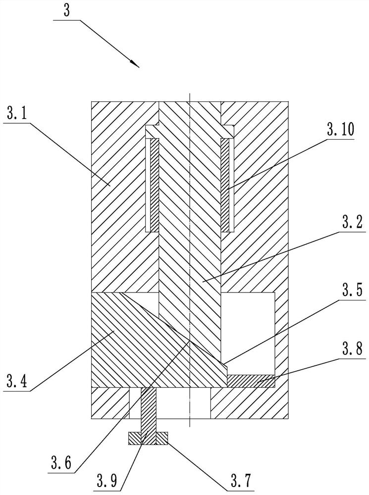
[0034] Such as image 3 As shown, the pushing assembly 3 further includes a third spring 3.10, one end of the third spring 3.10 is connected to the lifting block 3.2, and the other end of the third spring 3.10 is connected to the sliding and fixing block 3.1. The third spring 3.10 is a telescopic spring. The third spring 3.10 can make the lifting block 3.2 drop in time when the traverse block 3.4 retreats, so as to avoid the lifting block 3.2 from being stuck due to the effect of friction.

Embodiment 3

[0036] The first slope 3.5 is slidingly connected to the second slope 3.6 through a dovetail slider mechanism. The structure can make the traversing block 3.4 move together with the lifting block 3.2 to ensure stable switching between the two states and avoid the lifting block 3.2 from being stuck due to friction.


PUM


Abstract

The invention discloses a feeding and discharging pushing mechanism of a laser marking device. The feeding and discharging pushing mechanism comprises a supporting frame, a pushing driving mechanism, a pushing assembly and a tray. The pushing assembly comprises a sliding fixing block, a lifting block, a transverse moving block and a second spring; the lifting block is in sliding connection with the sliding fixing block; the transverse moving block is in sliding connection with the sliding fixing block; a first inclined face is arranged on the lifting block; a second inclined face is arranged on the transverse moving block; a guide plate is arranged on the supporting frame; a first guide long groove, a partition plate, a second guide long groove, a first shifting rod and a first spring are arranged on the guide plate side by side; the two ends of the first guide long groove are communicated with the two ends of the second guide long groove through communicating grooves; a shifting block is arranged below the transverse moving block; and the shifting block and the transverse moving block are fixedly connected. According to the feeding and discharging pushing mechanism of the laser marking device, the automatic feeding and discharging conveying function can be achieved, and meanwhile the problem that parts and equipment are damaged due to the fact that the lifting block retracts and stretches out unduly can be solved.

Description

technical field [0001] The invention relates to the technical field of laser marking machines, in particular to a loading and unloading mechanism of a laser marking device. Background technique [0002] The loading and unloading of existing laser marking machines is generally carried out manually. The trays with products are placed on the conveyor line in turn, and transported to the bottom of the laser marking machine through the conveyor line for marking. However, the manual feeding method has the problems of low feeding efficiency and high labor cost. Therefore, the present application designs a laser marking device loading and unloading and pushing mechanism, which can realize the function of automatically pushing materials during the automatic feeding process. [0003] Chinese Patent Application Publication No. CN207658787U, published on July 27, 2018, titled "An Automatic Feeding Mechanism for a Roll-in and Unwinder", discloses an automatic feeding mechanism for a Rol...

Claims


Application Information

Patent Timeline
Patent Type & Authority Applications(China)
IPC IPC(8): B23K26/70B23K26/362
CPCB23K26/702B23K26/362
Inventor 丁济松
Owner NINGBO BEILONG PRECISION MOLDING
Why Eureka
Try Eureka