
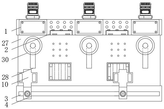
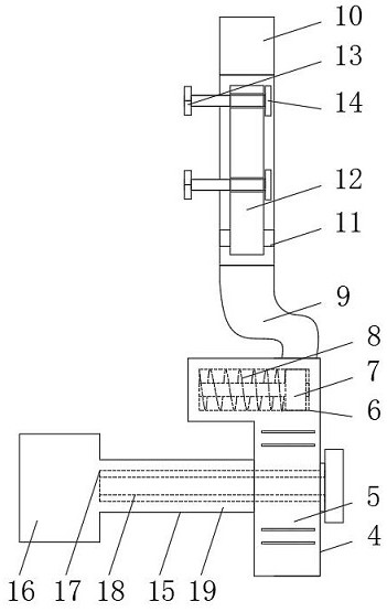
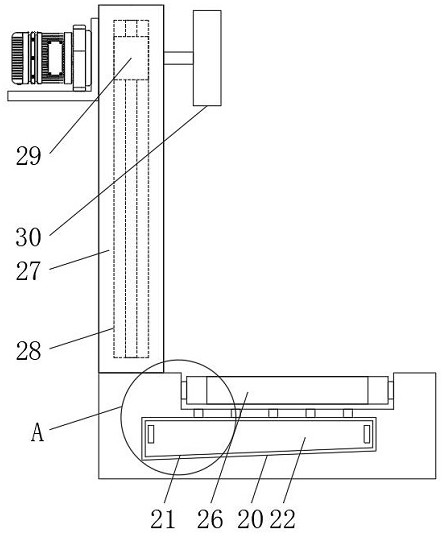
Grinding device facilitating fixed-point deburring for printer shell production

A technology for printers and deburring, applied in grinding drives, grinding machines, grinding racks, etc., can solve problems such as hidden safety hazards, inconvenient grinding, and inability to grind parts with a high degree of fit

Pending Publication Date: 2021-05-28
东莞市迈能达自动化科技有限公司
View PDF0 Cites 0 Cited by
  • Summary
  • Abstract
  • Description
  • Claims
  • Application Information

AI Technical Summary

Problems solved by technology

[0004] The purpose of the present invention is to provide a convenient fixed-point deburring and grinding device for the production of printer shells, so as to solve the problem that the existing devices proposed in the background technology cannot be used to adjust the height of the grinding parts, resulting in grinding At the same time, it is not convenient enough, and at the same time, it is impossible to polish the burr at a fixed point, and at the same time, the processed object cannot be moved and used by relying on the grinding device, resulting in a large safety hazard during processing, and the convenience is also poor.

Method used


Image

  • Grinding device facilitating fixed-point deburring for printer shell production
  • Grinding device facilitating fixed-point deburring for printer shell production
  • Grinding device facilitating fixed-point deburring for printer shell production

Examples


Embodiment Construction

[0026] The following will clearly and completely describe the technical solutions in the embodiments of the present invention with reference to the accompanying drawings in the embodiments of the present invention. Obviously, the described embodiments are only some, not all, embodiments of the present invention.

[0027] In the description of the present invention, unless otherwise stated, the meaning of "plurality" is two or more; the terms "upper", "lower", "left", "right", "inner", "outer" , "front end", "rear end", "head", "tail", etc. indicate the orientation or positional relationship based on the orientation or positional relationship shown in the drawings, and are only for the convenience of describing the present invention and simplifying the description, rather than Indicates or implies that the device or element referred to must have a particular orientation, be constructed and operate in a particular orientation, and therefore should not be construed as limiting the...


PUM


Abstract

The invention relates to a grinding device facilitating fixed-point deburring for printer shell production. The grinding device comprises an outer base and an exchange mechanism, buckle boxes are installed on the left end wall and the right end wall of the outer base correspondingly, a lower channel is formed in the front wall of the lower end of the outer base, the exchange mechanism is arranged at the outer side of the lower channel, and a lower group mechanism is installed at the bottom end side of the exchange mechanism. The grinding device has the beneficial effects that according to the grinding device facilitating fixed-point deburring for printer shell production, the position of a sliding block in a groove can be adjusted through embedded movement between a base groove and the sliding block in the groove, and at the moment, the sliding block in the groove can be conveniently linked with a connecting base to adjust the position; and when the connecting base is fitted relative to a body, materials at the end of the connecting base can be simply clamped, the materials are limited by depending on the end of the body, grinding machining operation is facilitated, the connecting base can be linked for springing through the elastic force of a spring column in the groove, the connecting base has the automatic springing and fitting effect, and the machined materials can be better limited conveniently.

Description

technical field [0001] The invention relates to the technical field of printer processing, in particular to a fixed-point deburring and grinding device for printer casing production. Background technique [0002] Printer (Printer) is one of the output devices of the computer. It is used to print the results of computer processing on related media. There are three indicators to measure the quality of the printer: printing resolution, printing speed and noise. There are many types of printers, according to printing components Whether there is an impact action on the paper, it is divided into impact printers and non-impact printers, according to the structure of printed characters, it is divided into full-size character printers and dot-matrix character printers, and according to the way a line of characters is formed on paper, it is divided into serial printers Compared with line printers, grinding devices are generally required for processing. [0003] The existing device ca...

Claims


Application Information

Patent Timeline
IPC IPC(8): B24B9/00B24B41/02B24B41/06B24B41/00B24B47/22B24B47/12B24B27/00
CPCB24B9/00B24B27/0076B24B41/005B24B41/02B24B41/06B24B47/12B24B47/22
Inventor 李文燕郑胜锋许焕章
Owner 东莞市迈能达自动化科技有限公司
Learn More