Antenna housing, antenna housing mold and preparation method of antenna housing

A technology of radome and mold, which is applied in the field of mold manufacturing, can solve the problems of mold manufacturing cost increase, production efficiency reduction, low dielectric constant, etc., and achieve the effects of reducing marginal cost, saving production cost and reducing manufacturing cost

Active Publication Date: 2021-05-28
COMBA TELECOM TECH (GUANGZHOU) CO LTD +1
View PDF5 Cites 2 Cited by
  • Summary
  • Abstract
  • Description
  • Claims
  • Application Information

AI Technical Summary

Problems solved by technology

However, since the mold is a precision instrument, its design and manufacture are very difficult, and it is difficult to manufacture a mold that meets the requirements and is suitable for manufacturing the above-mentioned radome.
[0009] CN103407018B Patent Announcement proposes a radome mold to partially solve the above-mentioned problems. Although the mold can be manufactured with a lower dielectric constant and a lower dielectric loss factor, and can withstand high temperatures, it is a low dielectric, Low-loss radome, but there are still problems in practice: First, the mold is suitable for compression molding to manufacture radome, but compression molding is easily limited by the length of the mold, so that the mold cannot be used to produce larger radome
Second, the molds used for compression molding cannot be continuously generated, resulting in a reduction in production efficiency, and the limitations of the molds, which cannot maximize the production efficiency
Third, the production and processing of molds suitable for compression molding is difficult, which leads to an increase in mold manufacturing costs

Method used


Image

  • Antenna housing, antenna housing mold and preparation method of antenna housing
  • Antenna housing, antenna housing mold and preparation method of antenna housing
  • Antenna housing, antenna housing mold and preparation method of antenna housing

Examples


Embodiment Construction

[0067] Embodiments of the present invention are described in detail below, examples of which are shown in the drawings, wherein the same or similar reference numerals denote the same or similar elements or elements having the same or similar functions throughout. The embodiments described below by referring to the figures are examples, and are only for explaining the present invention and should not be construed as limiting the present invention.

[0068] Those skilled in the art will understand that unless otherwise stated, the singular forms "a", "an", "said" and "the" used herein may also include plural forms. It should be further understood that the word "comprising" used in the description of the present invention refers to the presence of said features, integers, steps, operations, elements and / or components, but does not exclude the presence or addition of one or more other features, integers, steps, operations, elements and / or components, but does not preclude the pres...


PUM

PropertyMeasurementUnit
thicknessaaaaaaaaaa
densityaaaaaaaaaa
densityaaaaaaaaaa

Abstract

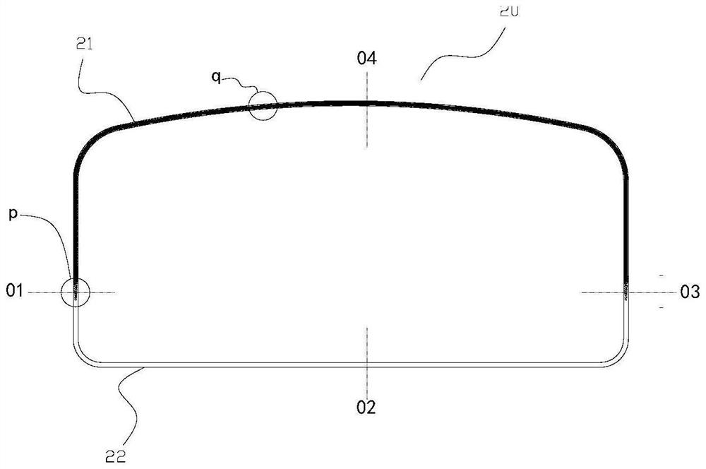
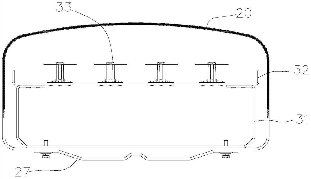
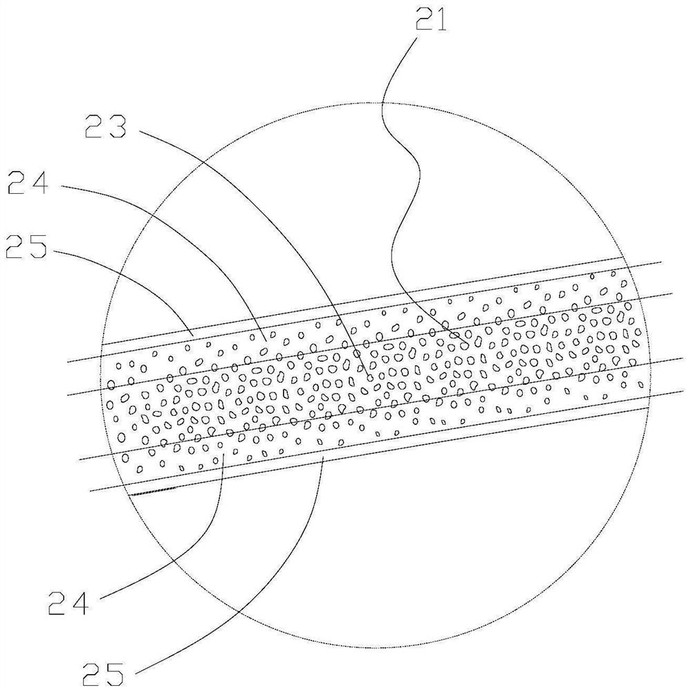
The invention discloses an antenna housing, antenna housing mold and preparation method of antenna housing. The antenna housing mold comprises a mold head and a shaping mold; the mold head comprises an annular mold cavity, an upper material injection channel and a lower material injection channel, the annular mold cavity comprises an upper mold cavity and a lower mold cavity which are communicated with the upper material injection channel and the lower material injection channel respectively, and the upper mold cavity is locally provided with an adjusting section used for reducing the space of the material channel in the axial direction; and the shaping mold comprises a shaping cavity arranged corresponding to the upper mold cavity, the shaping cavity is jointly limited by an outer mold and an inner mold, and the inner mold and/or the outer mold are/is used for conducting heat so as to heat materials passing through the shaping cavity. The antenna housing mold disclosed by the invention can be suitable for manufacturing integrally formed antenna housings with good dielectric properties and mechanical properties on a large scale.

Description

technical field [0001] The invention belongs to the technical field of mold manufacturing, and in particular relates to a radome mold, a radome adapted to the radome mold, and a preparation method for the radome. Background technique [0002] In the 5G era, the base station antennas take Massive MIMO active antennas, active-passive integrated antennas, and ultra-multi-system integrated passive antennas as the mainstream technology direction, and their technical complexity far exceeds that of the 2G, 3G, and 4G eras. For the radiating unit / array of each subsystem in the base station antenna system, its boundary conditions are becoming more and more complicated, and the technical difficulty of electrical performance design is becoming more and more difficult. [0003] The radome is an important part of the base station antenna. It not only protects the internal components of the antenna device, but also the dielectric properties of its structure and materials have a direct imp...

Claims


Application Information

Patent Timeline
Patent Type & Authority Applications(China)
IPC IPC(8): B29C44/58B29C44/04B29C44/06H01Q1/42
CPCB29C44/58B29C44/06B29C44/0461H01Q1/424
Inventor 肖飞卜斌龙薛锋章刘培涛
Owner COMBA TELECOM TECH (GUANGZHOU) CO LTD
Why Eureka
Try Eureka